
Lens driving device

A lens driving device and lens technology, applied in the direction of electromechanical devices, installation, electric components, etc., can solve problems affecting electromagnetic induction, etc., and achieve the effects of improved electromagnetic induction force, high assembly quality and assembly efficiency

Inactive Publication Date: 2010-06-16
NINGBO JCT ELECTRONICS
View PDF0 Cites 15 Cited by
  • Summary
  • Abstract
  • Description
  • Claims
  • Application Information

AI Technical Summary

Problems solved by technology

[0002] There are many types of existing lens driving devices that are matched to miniature cameras, such as Chinese Patent Application No. 2008200023412 "A Lens Driving Device", which includes a square profile with a round hole on the base and is also used as a lens driving device. The yoke ring of the external frame of the device, the magnet and the coil are placed in the yoke ring, the lens with a lens carrier is arranged in the round hole of the yoke ring, and the front and rear of the lens carrier are respectively provided with front gaskets. Front side spring and rear side spring with rear side spacer, the wire shape of the front and rear side springs is symmetrical up and down, left and right, to eliminate the rotation deviation caused by deformation, and prevent the slight optical axis deviation when the lens carrier moves; the magnet is set as a triangle Prismatic and placed on the four corners of the square outline of the yoke ring; the Chinese Patent Application No. 2008200023412 "A Lens Driving Device" has a large electromagnetic induction force and good electrical and mechanical properties; however, it does not It is suitable for the supporting application of the lens driving device with the front and rear frames with snap sockets; in addition, the inner circle and outer square inner cavity structure of the yoke ring in the Chinese Patent Application No. 2008200023412 "A Lens Driving Device" restricts the The size configuration between the magnet and the coil, thereby affecting the further expansion of the intensity of the electromagnetic induction

Method used


Image

  • Lens driving device
  • Lens driving device
  • Lens driving device

Examples


Embodiment Construction

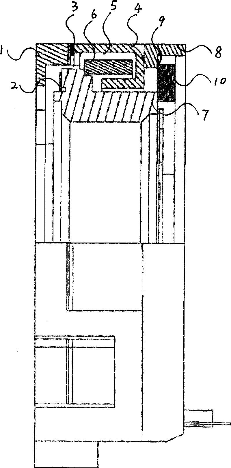
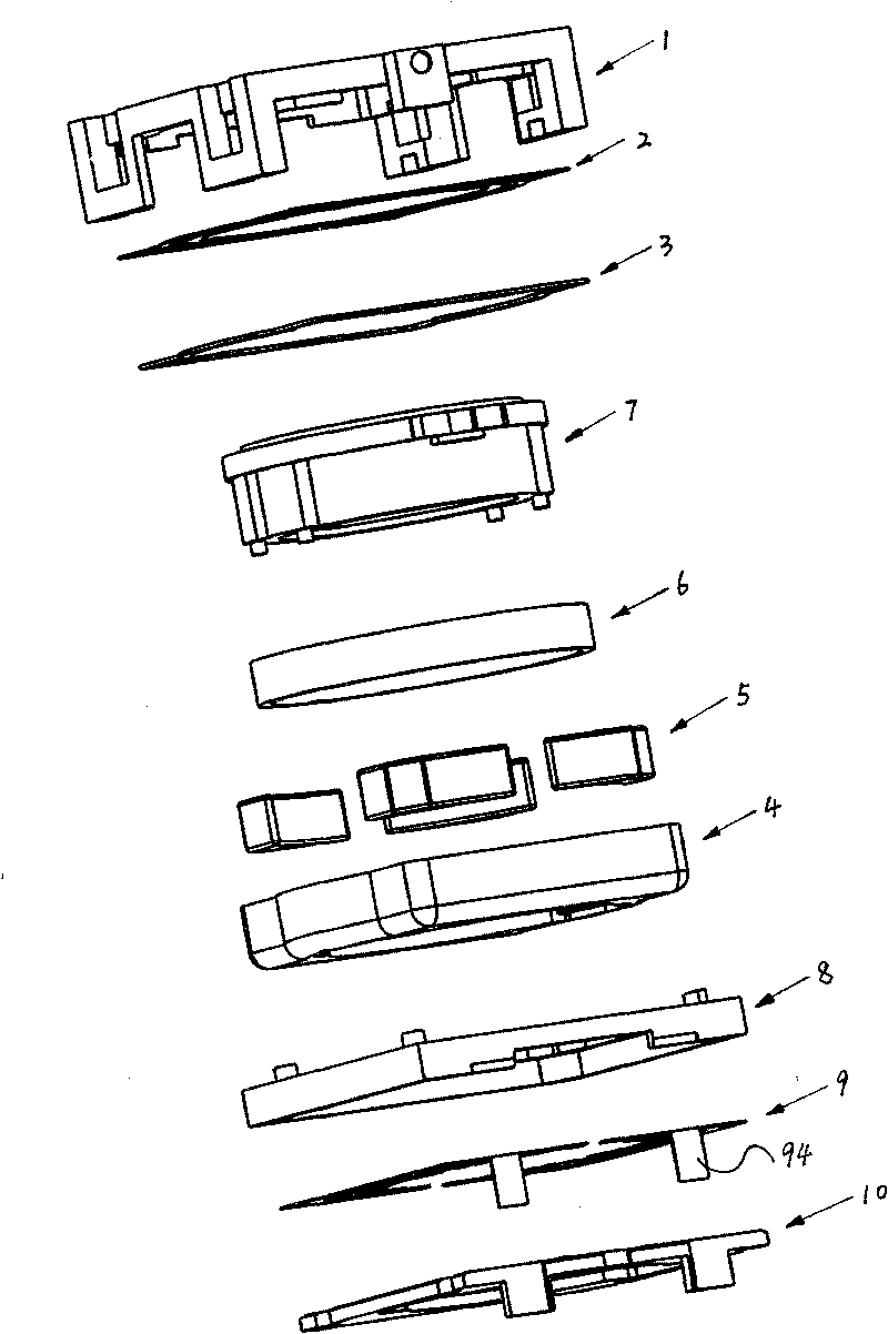
[0024] The present invention will be further described in detail below in conjunction with the accompanying drawings and embodiments.

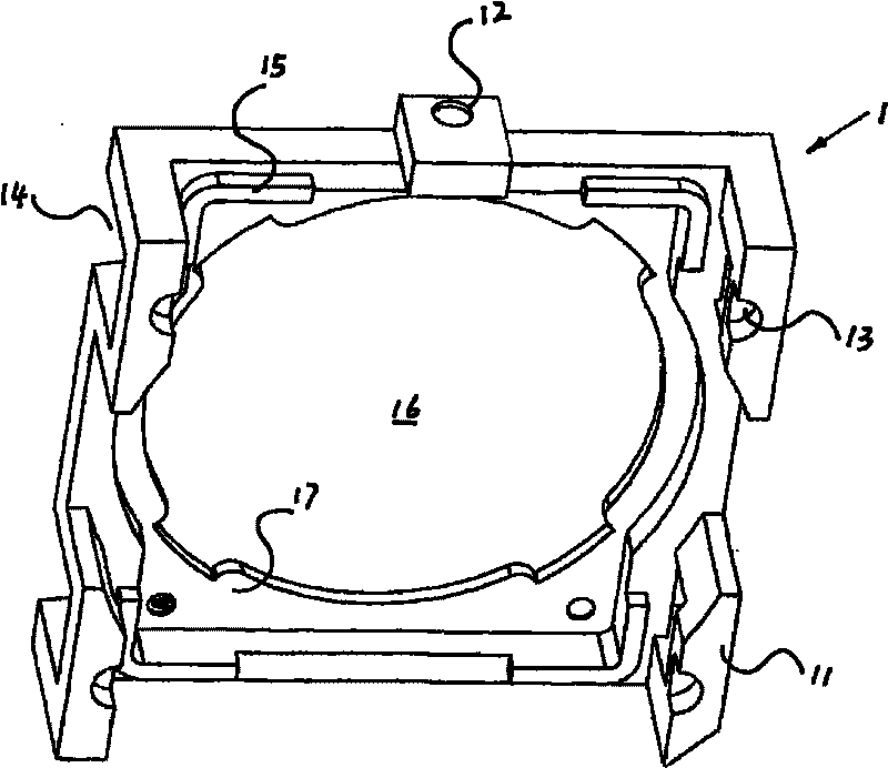
[0025] Such as Figure 1 to Figure 8 An embodiment of the present invention is shown, which includes a front frame 1 and a rear frame 8 corresponding to the front frame 1 . The front frame 1 is provided with a central through hole 16 and an outer projection 12; two clips 11 are symmetrically arranged on the two outer sides of the front frame; There are semicircular positioning holes 13.

[0026] The top of the front frame is provided with a rectangular inner end surface 17 with circular arcs on both sides, and an "L" shaped convex strip 15 is respectively arranged on the four corners of the inner end surface, and the position of the convex strip 15 corresponds to the clip 11 .

[0027] The rear frame 8 is set as a frame structure, and the two sides of the rear frame 8 are respectively provided with two semicircular projections 83, and the se...


PUM


Abstract

The invention relates to a lens driving device, comprising a magnet yoke ring with a lodestone; the magnet yoke ring is arranged between a front frame and a back frame and is provided with a cylindrical lens supporter with coil; the front part of the lens supporter is provided with a front backup plate and a front spring, the back part thereof is provided with a back spring; in addition, the magnet yoke ring is also provided with arc rectangular outer frames at two sides, the outer frames are provided with a circular vertical convex edge with two symmetrically arranged openings, a rectangular inner chamber with arcs arranged at two sides is formed between the outer frames and the vertical convex edge; the lodestone is of a trapezoid shape provided with arc bottom edges and asymmetric beveled edge and is provided with a magnet yoke ring in-circle end face; the lens supporter is arranged on the in-circle end face, the external diameter is matched with the internal diameter of the circular vertical convex edge of the magnet yoke ring; a front frame and a back frame, a supporter and a foundation are all made from engineering plastics by injection moulding; in the invention, electromagnetic induction force is remarkable improved, further product microminiaturization can be facilitated at high assembly accuracy and assembly efficiency.

Description

technical field [0001] The invention relates to the field of a miniature camera; in particular, it relates to a lens driving device specially matched with the miniature camera. Background technique [0002] There are many types of existing lens driving devices that are matched to miniature cameras, such as Chinese Patent Application No. 2008200023412 "A Lens Driving Device", which includes a square profile with a round hole on the base and is also used as a lens driving device. The yoke ring of the external frame of the device, the magnet and the coil are placed in the yoke ring, the lens with a lens carrier is arranged in the round hole of the yoke ring, and the front and rear of the lens carrier are respectively provided with front gaskets. Front side spring and rear side spring with rear side spacer, the wire shape of the front and rear side springs is symmetrical up and down, left and right, to eliminate the rotation deviation caused by deformation, and prevent the sligh...

Claims


Application Information

Patent Timeline
IPC IPC(8): G02B7/04H02K33/18
CPCH02K41/0356G02B7/08
Inventor 王在伟林聪
Owner NINGBO JCT ELECTRONICS
Learn More