Method for testing memory

A test method and memory technology, applied in static memory, instruments, etc., can solve problems such as the decline in pass rate, and achieve the effects of small load, less data transmission, and short test time

Active Publication Date: 2010-06-16
PROLIFIC TECH INC
View PDF0 Cites 12 Cited by
  • Summary
  • Abstract
  • Description
  • Claims
  • Application Information

AI Technical Summary

Problems solved by technology

If it is treated in a non-discriminatory manner, ...

Method used


Image

  • Method for testing memory
  • Method for testing memory
  • Method for testing memory

Examples


Embodiment Construction

[0047] In order to make the technical problems, technical solutions and advantages to be solved by the embodiments of the present invention clearer, the following will describe in detail with reference to the drawings and specific embodiments.

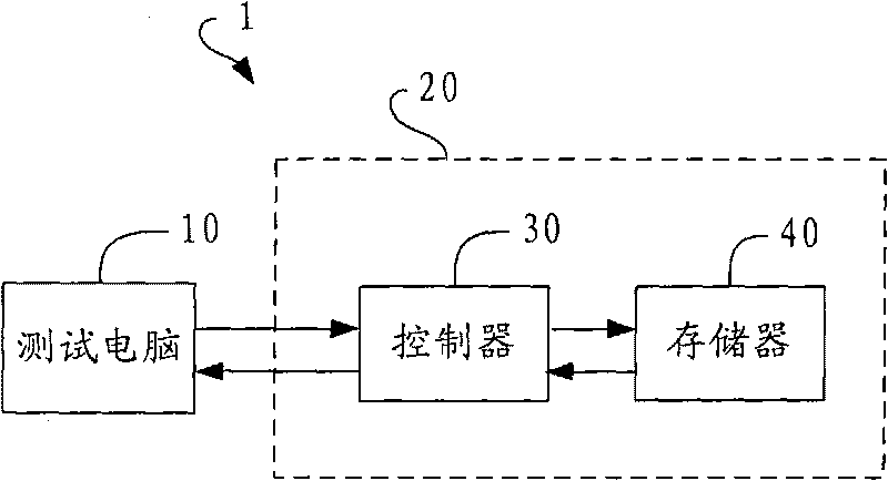
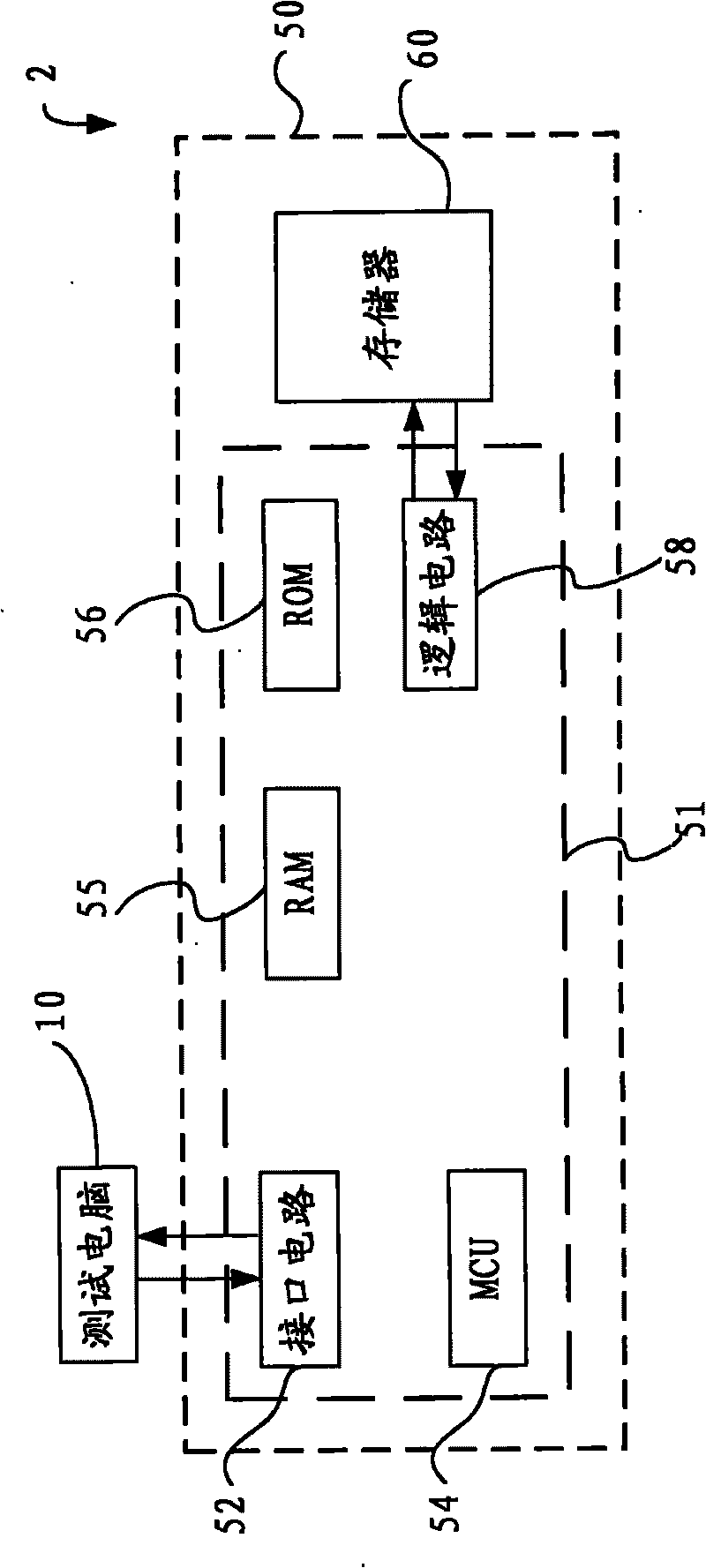
[0048] image 3 It is a schematic diagram of the test method of the memory of the present invention. Such as image 3 As shown, the memory testing system 2 includes a testing computer 10 and a screening board 50 , wherein the screening board 50 includes a controller 51 and a memory 60 to be tested. Controller 51 includes interface circuit 52, microprocessor (MCU) 54, random access memory (RAM) 55, read-only memory (ROM) 56 and logic circuit 58, and interface circuit 52 is responsible for receiving the data of testing computer 10 or transmitting data To the test computer 10, the microprocessor 54 controls the processing program of the entire controller, the random access memory 55 provides access to temporary data, the logic circuit 58 ...


PUM


Abstract

The invention claims a method for testing a memory, comprising the steps as follows: aiming at a memory, generating random number data or generating testing data in specific format according to an algorithm by using the operation capacity of a controller after receiving a testing instruction and a program code sent by a testing computer; carrying out writing-in, reading-out and comparison operations of data on a flash memory; and delivering the test result to the testing computer. The testing speed of the memory is increased by greatly reducing the data input and output loads to the memory from the testing computer.

Description

technical field [0001] The invention relates to a method for testing a memory, in particular to using a built-in controller with a test function to test the memory. Background technique [0002] Flash memory is currently the most popular storage medium and is widely used in embedded systems. Flash memory is a solid-state, non-volatile, rewritable memory that operates like a hybrid of random access memory and hard disk. Like DRAM, flash memory stores bits of data in memory cells, but the data remains on the memory when the power is turned off. Because of its high speed, persistence, and low voltage requirements, flash memory is ideal for use in many devices, such as digital cameras , mobile phones, printers, PDAs, pagers, and tape recorders. [0003] refer to figure 1 It is a schematic diagram of a memory testing system in the prior art. Such as figure 1 As shown, the memory testing system 1 includes a testing computer 10 and a sorting board (Sorting Board) 20, wherein t...

Claims


Application Information

Patent Timeline
IPC IPC(8): G11C29/56
Inventor 陈桮棬詹立翔黄世铠
Owner PROLIFIC TECH INC
Why Eureka
Try Eureka