Three-phase synchronous reluctance motor

A reluctance motor, three-phase synchronization technology, applied in the field of electric motors, can solve the problems of high cost, not smooth output torque, and high electromagnetic noise, and achieve the effects of high material utilization, reduction of electromagnetic noise, and avoidance of output pulsating torque

Inactive Publication Date: 2010-06-16
DATONG COAL MINE GRP
View PDF0 Cites 0 Cited by
  • Summary
  • Abstract
  • Description
  • Claims
  • Application Information

AI Technical Summary

Problems solved by technology

[0003] The invention provides a three-phase synchronous reluctance motor in order to solve the problems of low material utilization rate, high electromagnetic noise, unsmooth output torque and high cost of the switched reluctance motor

Method used


Image

  • Three-phase synchronous reluctance motor
  • Three-phase synchronous reluctance motor
  • Three-phase synchronous reluctance motor

Examples


Embodiment Construction

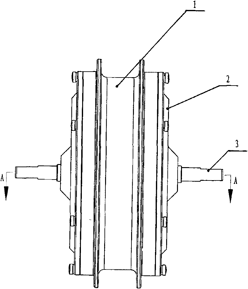
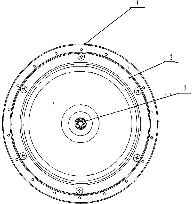
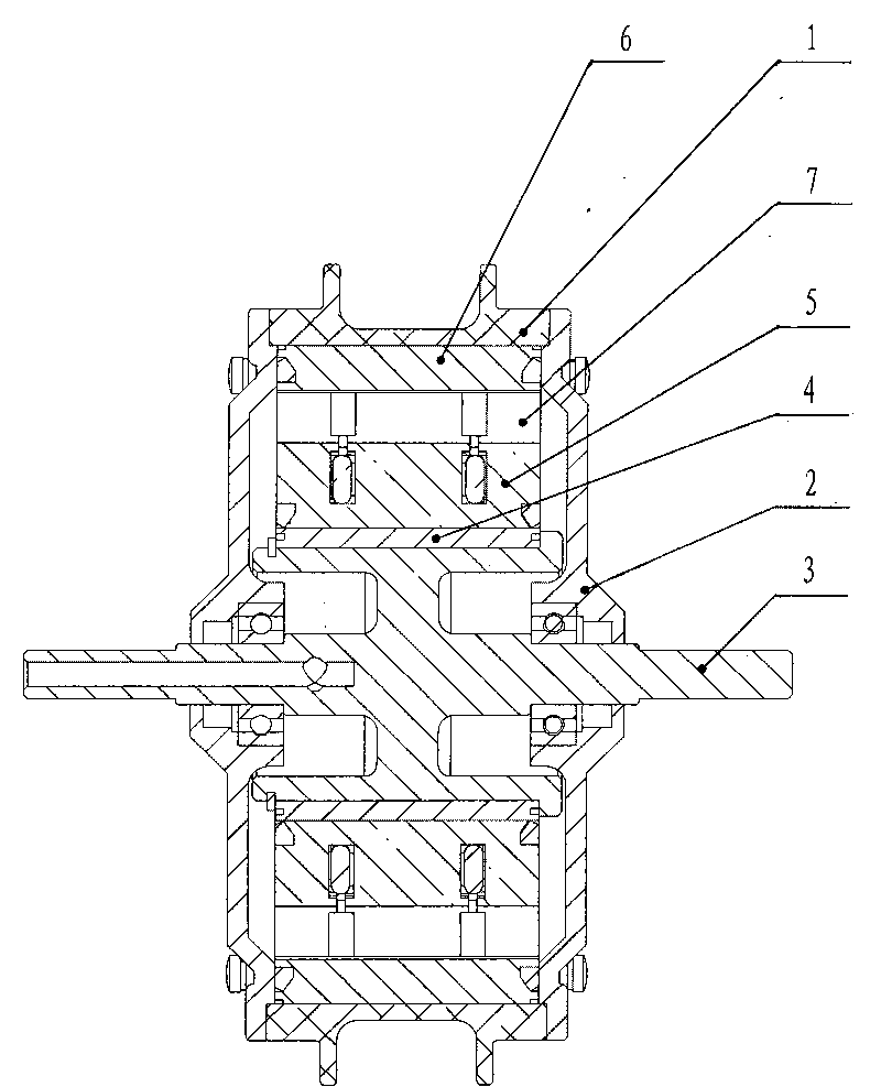
[0031] A three-phase synchronous reluctance motor, including a stator assembly, a rotor assembly, a wheel housing 1, an end cover 2 fixed at both ends of the wheel housing 1, and a stator shaft 3; the end cover 2 is supported on the end of the stator shaft 3 through a bearing; the stator assembly consists of The stator coil 4 fixed on the stator shaft 3, 6N (N is a natural number greater than or equal to 2) stator poles 5 fixed on the stator coil 4, and concentrated windings wound on each stator pole 5; the rotor assembly includes and The rotor ring 6 fixed by the wheel shell 1, the 7N (N is a natural number greater than or equal to 2) rotor poles 7 fixed on the rotor ring 6, and the permanent magnets fixed on the rotor poles 7; among the 6N concentrated windings, each consecutive The six concentrated windings of each group of six concentrated windings, the tail end of the first concentrated winding is connected with the tail end of the fourth concentrated winding as A-phase wi...


PUM


Abstract

The invention relates to a motor and in particular to a three-phase synchronous reluctance motor. The three-phase synchronous reluctance motor solves problems of low material use efficiency, loud electromagnetic noise, unsmooth output torque and high cost of a switched reluctance motor. The three-phase synchronous reluctance motor comprises a stator assembly, a rotor assembly, a hub, end covers which are fixed at the two ends of the hub and a stator shaft, wherein the end covers are supported at the end parts of the stator shaft by bearings; the stator assembly comprises a stator ring fixed on the stator shaft, 6 N stator poles fixed on the stator ring and concentrated windings wounded on each stator pole; and the rotor assembly comprises a rotor ring fixed with the hub, 7N rotor poles fixed on the rotor ring and permanent magnets fixed on the rotor poles. The motor of the invention is suitable to be used for not only driving an electro-mobile, a mine underground conveyor, a large-scale fan and the like but also a reversible mill, a flying saw, a flying shear and the like in double housing planer, milling machine and metallurgy industries.

Description

technical field [0001] The invention relates to a motor, in particular to a three-phase synchronous reluctance motor. Background technique [0002] In recent years, with the development of electronic technology, switched reluctance motors have gradually entered various production fields. The switched reluctance motor has the advantages of simple structure, low cost, high efficiency, low loss, high starting torque and low starting current. It is especially suitable for machines that require heavy-load starting and long-term low-speed and heavy-load operation, such as electric vehicles. At the same time, due to the frequent start and stop and forward and reverse conversion operation, the switched reluctance motor is also especially suitable for planer machines, milling machines, reversible rolling mills in the metallurgical industry, flying saws, flying shears, etc. However, switched reluctance motors also have many shortcomings: First, the material utilization rate of switch...

Claims


Application Information

Patent Timeline
IPC IPC(8): H02K29/00
CPCY02T10/641Y02T10/64
Inventor 崔振忠刘纯贵刘大同郭万忠庞晓梅
Owner DATONG COAL MINE GRP
Why Eureka
Try Eureka