

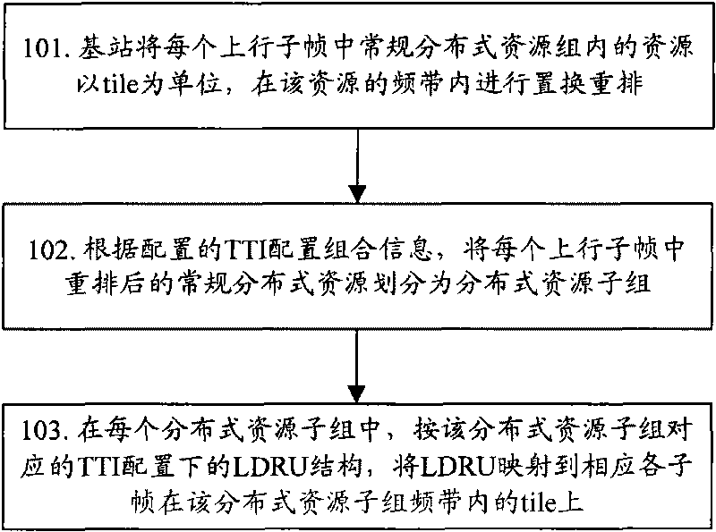
Method for sub-channelizing and mapping wireless resources
A technology of sub-resources and resources, which is applied in the field of wireless resource sub-channelization and mapping at different transmission time intervals, can solve the problems of no wireless resource sub-channelization and mapping schemes, proposals, etc., to meet business performance requirements and improve spectrum efficiency , the effect of fully and efficiently utilizing resources
- Summary
- Abstract
- Description
- Claims
- Application Information
AI Technical Summary
Problems solved by technology
Method used
Image

Examples
Embodiment 1
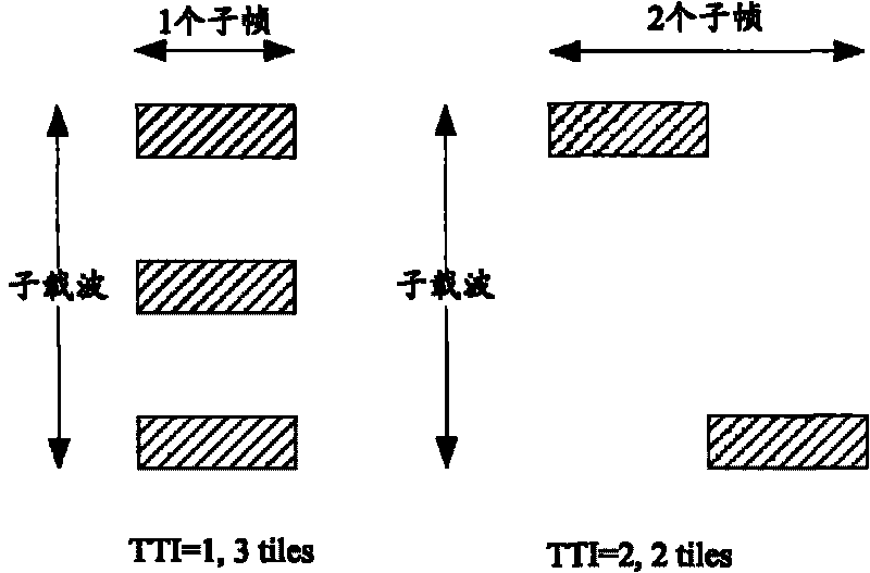
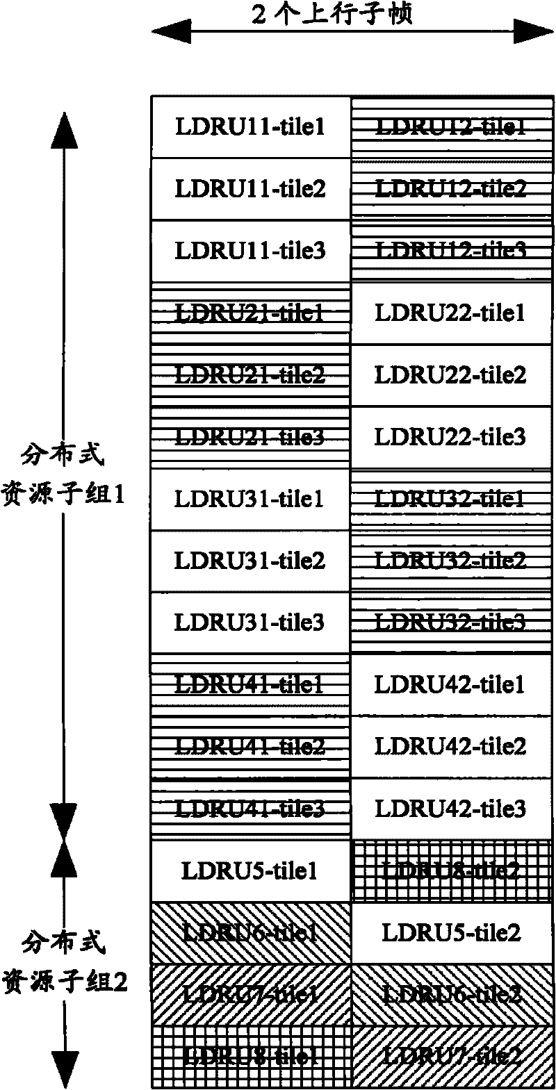
[0066] Assume that there are two uplink subframes in one radio frame, and the system sets two TTI configurations, namely TTI is one subframe and two subframes. Multiple tiles forming an LDRU under different TTI configurations are physically discretely distributed according to sub-channelization and corresponding resource block structures, such as figure 2 shown. Wherein, the LDRU whose TTI is one subframe is composed of three tiles; the LDRU whose TTI is two subframes is composed of two tiles, and each rectangle filled with oblique lines represents a tile. figure 2 The horizontal direction is the subframe, each subframe has 6 symbols, and the vertical direction is the subcarrier. figure 2 For illustrative purposes only, three tiles when the TTI is one subframe, and two tiles when the TTI is two subframes, does not mean continuous or equal intervals.
[0067] The base station divides the regular distributed resources into a distributed resource subgroup 1 and a distributed...
Embodiment 2
[0071] Assume that there are two uplink subframes in one radio frame, and the system sets two TTI configurations, namely TTI is one subframe and two subframes. Multiple tiles forming an LDRU under different TTI configurations are physically discretely distributed according to sub-channelization and corresponding resource block structures, such as Figure 4 shown. Among them, the LDRU whose TTI is one subframe is composed of three tiles; the LDRU whose TTI is two subframes is composed of four tiles, and each rectangle filled with oblique lines represents a tile. Figure 4 The horizontal direction is the subframe, each subframe has 6 symbols, and the vertical direction is the subcarrier. Figure 4 For illustrative purposes only, three tiles when the TTI is one subframe, and four tiles when the TTI is two subframes, does not mean continuous or equal intervals.
[0072] The base station divides the regular distributed resources into a distributed resource subgroup 1 and a distri...
Embodiment 3
[0076] Assuming that the number of uplink subframes in one radio frame is three, the system sets two TTI configurations, namely TTI is one subframe and three subframes. Multiple tiles forming an LDRU under different TTI configurations are physically discretely distributed according to sub-channelization and corresponding resource block structures, such as Figure 6 shown. Wherein, the LDRU whose TTI is one subframe is composed of three tiles; the LDRU whose TTI is three subframes is composed of three tiles, and each rectangle filled with oblique lines represents a tile. Figure 6 The horizontal direction is the subframe, each subframe has 6 symbols, and the vertical direction is the subcarrier. Figure 6 For illustrative purposes only, three tiles when the TTI is one subframe and three tiles when the TTI is three subframes do not mean continuous or equal intervals.
[0077] The base station divides the regular distributed resources into a distributed resource subgroup 1 and ...
PUM
 Abstract
Description
Claims
Application Information