Device and method for reducing CO2-emissions from the waste gases of combustion plants

An equipment and flue gas technology, which is applied in the field of devices and methods for reducing CO2 emissions in the exhaust gas of combustion equipment, and can solve problems such as blockage of membrane holes.

Inactive Publication Date: 2010-06-16
FORSCHUNGSZENTRUM JULICH GMBH
View PDF0 Cites 2 Cited by
  • Summary
  • Abstract
  • Description
  • Claims
  • Application Information

AI Technical Summary

Problems solved by technology

In devices that use membranes for flue gas decarbonization after wet flue gas desulfurization, the membrane pores associated with the membrane material can be unfavorably blocked by condensed water due to being below the condensation line of water vapor

Method used


Image

  • Device and method for reducing CO2-emissions from the waste gases of combustion plants
  • Device and method for reducing CO2-emissions from the waste gases of combustion plants
  • Device and method for reducing CO2-emissions from the waste gases of combustion plants

Examples


Embodiment Construction

[0025] The present invention is described in detail below with embodiment, but protection scope is not limited thereby. These and other similar variations would be considered within the scope of the invention by those skilled in the art.

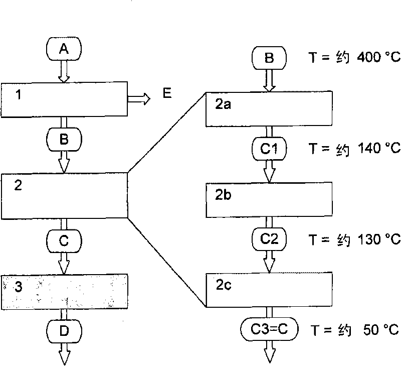
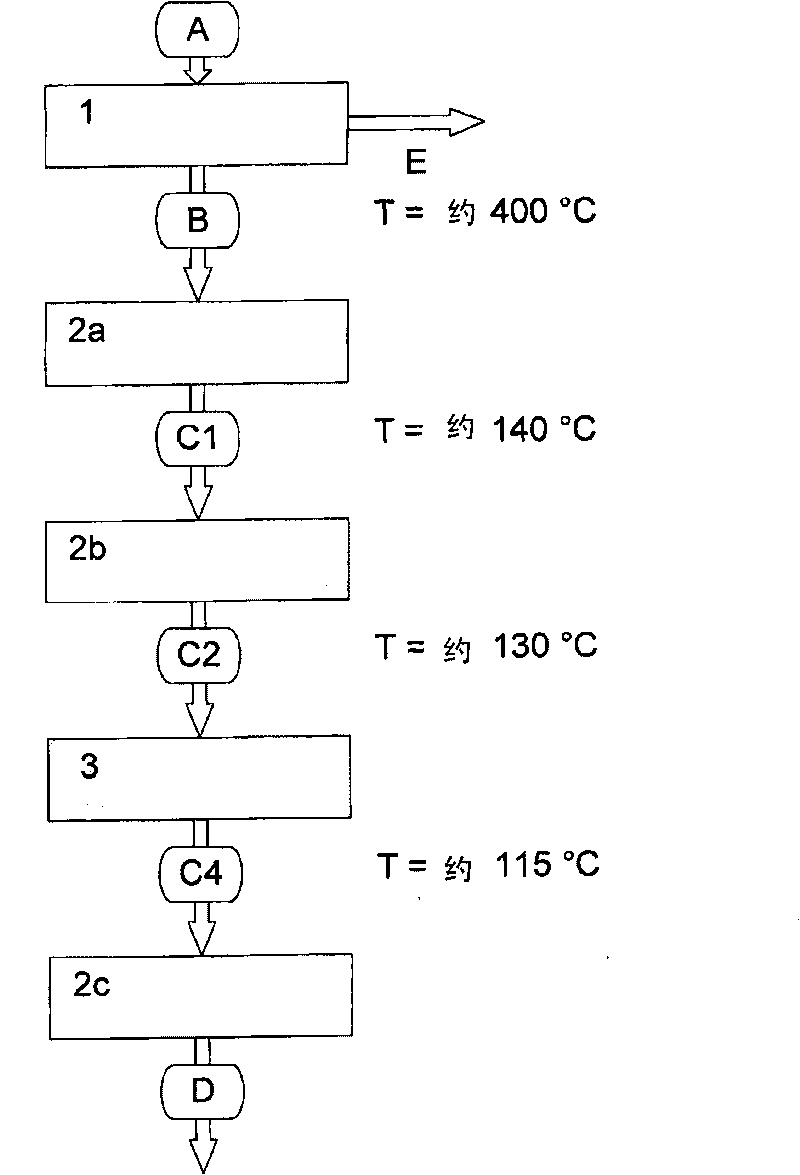
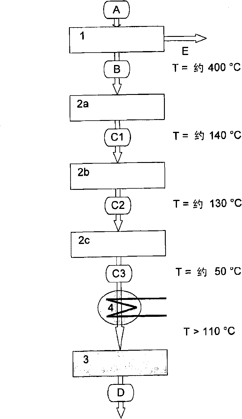
[0026] The ellipse in the figure means the medium:

[0027] A fuel

[0028] B Rough smoke

[0029] C Purified flue gas, where the difference is:

[0030] C1 denitrified flue gas,

[0031] C2 denitrified and dedusted flue gas, and

[0032] C3 denitrified, dedusted and desulfurized flue gas

[0033] D Pure flue gas = denitrified, dedusted, desulfurized and decarbonized flue gas,

[0034] E electricity

[0035] Rectangular boxes represent the various process steps:

[0036] 1 power generation

[0037] 2 Flue gas purification, currently includes:

[0038] 2a Nitrogen removal,

[0039] 2b dust removal, and

[0040] 2c Desulfurization

[0041] 3 CO through the membrane module 2 Separation (decarburization)

[0042] 4 heat transfer ...


PUM


Abstract

A method for separating carbon dioxide from a flue gas using a membrane (membrane module) is characterized in that the flue gas has temperatures above the dew line of the water vapor before entering the membrane separation stage. In this way, condensation of potentially entrained water vapor out of the flue gas is avoided, thereby regularly preventing clogging of the membrane pores. The high temperatures can be achieved in different ways. By connecting a heat exchanger or a burner upstream, the temperature of the flue gas can be easily increased to the necessary temperatures. A condenser, which is connected upstream of the membrane module and also advantageously increases the CO2 partial pressure, at the same time brings about the necessary temperature increase. As another alternative of the invention, the CO2 separation is performed even before desulfurizing the flue gas. This in particular has the advantage that the flue gas in this process stage still has temperatures above the condensate line of the water vapor, and therefore does not have to be heated separately, and in addition generally carries only little water vapor at this stage of the scrubbing operation.

Description

[0001] The present invention relates to the reduction of CO in the exhaust gases of combustion plants, in particular the flue gases of energy conversion plants, by means of membranes 2 Methods of discharging, and the invention also relates to devices suitable for carrying out such methods. Background technique [0002] One of the most important sources of increasing the concentration of carbon dioxide in the atmosphere is the burning of fossil energy carriers in combustion plants for energy production. Therefore, it is necessary to strive to separate the CO produced in the combustion of fossil energy carriers. 2 , and store after separation so as not to be released into the atmosphere. The reason for this effort is due to the greenhouse effect and resulting global warming. [0003] Among the various conceived methods, three basic principles for separating carbon dioxide have been drawn up at present, the difference lies in the different parts of the separation in the energy ...

Claims


Application Information

Patent Timeline
Patent Type & Authority Applications(China)
IPC IPC(8): B01D53/22C01B32/50
CPCY02C10/10B01D2257/504B01D53/229Y02C10/04B01D2257/30Y02C20/40
Inventor J·纳扎尔科E·里恩谢L·布卢姆R·门泽W·A·穆伦伯格M·布拉姆
Owner FORSCHUNGSZENTRUM JULICH GMBH
Why Eureka
Try Eureka