Pneumatic seed shooting and seeding device

The technology of a seeding device and a seeding device, which is applied in the field of agricultural machinery, can solve problems such as reducing the working efficiency of openers, difficulty in ensuring seeding quality, and unfavorable soil protection, so as to achieve environmental protection, reduce the number of plowing times, and reduce energy consumption. The effect of consumption

Inactive Publication Date: 2010-06-23
SHANDONG UNIV OF TECH
View PDF0 Cites 25 Cited by
  • Summary
  • Abstract
  • Description
  • Claims
  • Application Information

AI Technical Summary

Problems solved by technology

The traditional contact sowing method (direct contact between the opener and the soil) cannot meet the requirements of various advanced agronomic technologies developed in recent years, such as film mulching sowing, precision agriculture, water-saving agriculture and liquid fertilizer fertilization, etc.; Due to the direct interaction between the soil-entry device and the soil, the power consumption is relatively large; when the soil humidity is high, it is difficult to ensure the quality of the seed or even sow; However, there is a distance of the distance between the plants, so that the seed ditch between the plants is not used, which reduces the working efficiency of the opener, and the soil is also plowed when the ditch is opened, which is not conducive to soil protection. If the seeds can be directly sown Into the land, that is, the ditching process is eliminated, and energy saving can also prevent the soil from being plowed repeatedly

Method used


Image

  • Pneumatic seed shooting and seeding device
  • Pneumatic seed shooting and seeding device
  • Pneumatic seed shooting and seeding device

Examples


Embodiment Construction

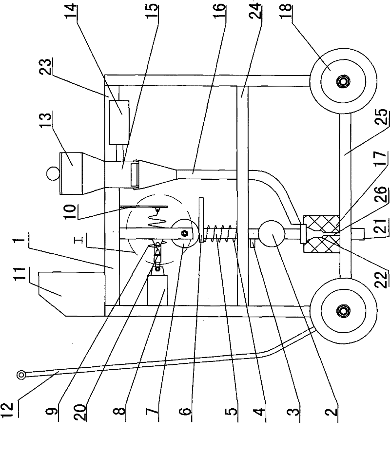
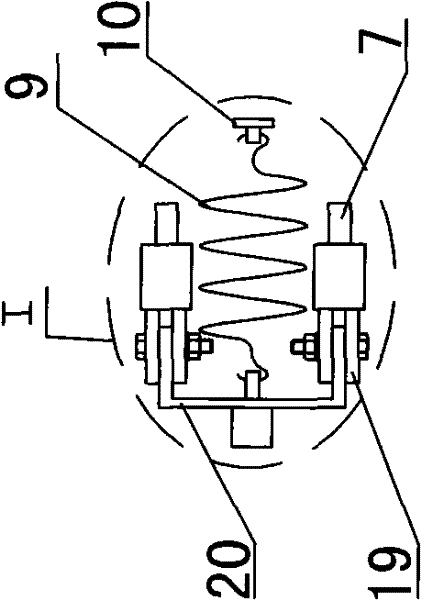
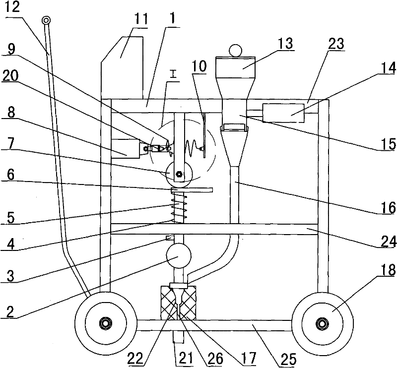
[0013] Such as Figure 1-2 In the shown embodiment: the PLC controller 11, the seed box 13 and the stepper motor 14 are all installed on the upper partition 23 of the frame 1, the hole seed meter 15 is installed at the bottom of the seed box 13, and the bottom is provided with a Seed tube 16, the output shaft connection type hole seed meter 15 of the stepper motor 14; the drive module includes a traction electromagnet 8 fixed on the frame 1, two swing bars whose upper end is hinged with the upper partition plate 23 beam of the frame 1 19. The locking wheel 7, the grooved rocker arm 20, the tension spring 9, and the pull plate 10 fixed at the bottom of the upper partition 23 of the frame 1 are connected by a shaft at the lower end of each swing rod 19, in which the traction electromagnet 8 The control terminal of the control terminal is connected to the PLC controller 11, and the two arms of the grooved rocker arm 20 are respectively connected to the two swing rods 19 shafts, a...


PUM


Abstract

The present invention provides a pneumatic seed shooting and seeding device. The device comprises a machine frame provided with travelling wheels and a seeding device arranged on the machine frame, wherein the seeding device comprises a seed box, a typical hole seeding apparatus, a seed guide pipe and a stepping motor, the seed box is arranged on the machine frame, the typical hole seeding apparatus is arranged on the bottom of the seed box, the seed guide pipe is communicated with the typical hole seeding apparatus, and the stepping motor is connected with the typical hole seeding apparatus. The present invention is characterized in that a pneumatic seed shooting device and a PLC (programmable logic control) controller are additionally arranged, and the control end of the stepping motor is connected with the PLC controller; the pneumatic seed shooting device comprises a drive module, a pneumatic seed shooting module and an accelerating tube, wherein the pneumatic seed shooting module is vertically arranged on the middle lower part of the machine frame in a movable mode, the top end is connected with the bottom of the drive module, the control end of the drive module is connected with the PLC controller, and the accelerating tube is fixed on the bottom of the pneumatic seed shooting module. The device directly sows seeds without adopting a ditching device and a soil covering device in a traditional seeder. The device has excellent work performance.

Description

technical field [0001] The invention provides a pneumatic seeding and sowing device for realizing shooting and sowing with high-pressure gas, which belongs to the technical field of agricultural machinery. Background technique [0002] The currently used hole sowing seeder mainly completes the work of ditching, seeding, fertilizer discharge, covering soil and compaction. When the seeder is working, the opener opens a seed ditch on the ground, and the seeds in the seed box are discharged by the seed meter and fall into the seed ditch through the seed delivery pipe. The traditional contact sowing method (direct contact between the opener and the soil) cannot meet the requirements of various advanced agronomic technologies developed in recent years, such as film mulching sowing, precision agriculture, water-saving agriculture and liquid fertilizer fertilization, etc.; Due to the direct interaction between the soil-entry device and the soil, the power consumption is relatively ...

Claims


Application Information

Patent Timeline
Patent Type & Authority Applications(China)
IPC IPC(8): A01C7/18
CPCY02P60/00Y02P60/20
Inventor 刁培松杜瑞成袁彩云
Owner SHANDONG UNIV OF TECH
Why Eureka
Try Eureka