Beam-pumping unit

A beam-type pumping unit and oil-pumping unit technology, which is applied to liquid variable-capacity machinery, mechanical equipment, machines/engines, etc. The effect of solving technical defects, reducing installed power and reducing the impact of the power grid

Inactive Publication Date: 2010-06-23
CHINA UNIV OF PETROLEUM (BEIJING)
View PDF0 Cites 5 Cited by
  • Summary
  • Abstract
  • Description
  • Claims
  • Application Information

AI Technical Summary

Problems solved by technology

It can be seen from the calculation that the use of this motor will lose 4029 kWh/year of active power and 17082 kW

Method used


Image

  • Beam-pumping unit
  • Beam-pumping unit
  • Beam-pumping unit

Examples


Example Embodiment

[0030] The technical solutions of the present invention will be further described in detail below through the accompanying drawings and embodiments.
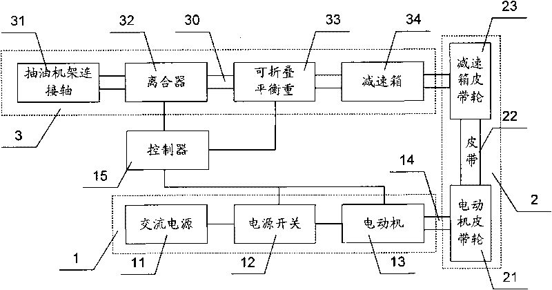
[0031] figure 1 It is a schematic diagram of the structure of the beam pumping unit of the present invention. like figure 1 As shown, the main structure of the beam pumping unit of the present invention includes a motor device 1, a transmission device 2 and a pumping unit device 3 with a foldable counterweight. The motor device 1, the transmission device 2 and the pumping unit device 3 are sequentially The transmission connection enables the motor unit 1 to drive the pumping unit unit 3 to run through the transmission unit 2. The motor device 1 of the present invention includes an AC power source 11 , a power switch 12 and a motor 13 that are electrically connected in sequence, and the motor 13 is drivingly connected to the transmission device 2 through a motor shaft 14 . The transmission device 2 includes a motor pulley 21 ,...


PUM


Abstract

The invention relates to a beam-pumping unit, which includes a motor, an actuating device and a pumping unit device connected in sequence; the pumping unit device comprises the connection shaft of the frame of the pumping unit, a foldable balancing weight, and a clutch which disconnects the connection shaft of the frame of the pumping unit and the foldable balancing weight when starting the motoras well as reconnects the connection shaft of the frame of the pumping unit and the foldable balancing weight when starting the pumping unit. The foldable balancing weight is set to be under an unfolded state when starting the motor, and under the folded state when starting the pump unit. The beam-pumping unit breaks through the design concept of the current pumping unit, sets the balancing weight of a 'monolithic block' pumping unit into the foldable balancing weight, and uses a mechanical energy storing principle to improve the efficiency of the motor of the pumping unit. The beam-pumping unit not only can reduce the installed power of the motor of the pumping unit to radically solve the technical defect of 'big Marathi car' of the motor of the pumping oil in the oil field, and also canimprove the efficiency of the motor during the running process of the pumping unit, and reduce the impact on power systems.

Description

technical field [0001] The invention relates to a beam pumping unit, in particular to a beam pumping unit with a foldable balance weight. Background technique [0002] The beam pumping unit is one of the important working equipment in the oil field. When working, each beam pumping unit needs to be equipped with a corresponding induction motor. Since the squirrel cage rotor induction motor (hereinafter referred to as the motor) has the advantages of simple structure, reliable operation, and low cost, the motor is widely used in oil field pumping. In the oil machine. [0003] The pumping unit in the oil field is different from the general load. The pumping unit is in the pumping state during the upstroke, the load is large, and the output of the motor is also large; during the downstroke, the pumping unit basically does not work, the load is small, and the output of the motor is also small. In order to balance these two working states, the pumping unit generally has a counte...

Claims


Application Information

Patent Timeline
IPC IPC(8): E21B43/00F04B47/14
Inventor 梁志珊王婷婷
Owner CHINA UNIV OF PETROLEUM (BEIJING)
Why Eureka
Try Eureka