Quick fluid-discharge technology

A fast and advanced technology, applied in the direction of mining fluid, wellbore/well components, earthwork drilling and production, etc., can solve problems such as shallow lifting depth, low efficiency, incomplete drainage, etc., to improve operating speed and efficiency, and improve operation Low cost and easy construction

Inactive Publication Date: 2010-06-23
胜利油田东润科工贸有限责任公司
View PDF0 Cites 2 Cited by
  • Summary
  • Abstract
  • Description
  • Claims
  • Application Information

AI Technical Summary

Problems solved by technology

At present, there are two main types of liquid drainage technologies commonly used: one is to insert tools such as pumps into the downhole tubing, and the well equipment drives the pumps to reciprocate up and down to drain the downhole liquid to the ground. Due to the limitation of the lowering depth, this technology has the problems of low efficiency, shallow lifting depth and incomplete drainage
The second type is to use gas lift to lift the well fluid to the surface, such as injecting high-pressure air or liquid nitrogen into the well, and supporting tools such as downhole gas lift valves, and using low specific gravity gas to lift the well fluid to the ground during the ascent process. On the ground, the supporting equipment and ground construction equipment implemented by this type of technology are complicated and expensive, and cannot be applied to various drainage needs at the same time

Method used


Image

  • Quick fluid-discharge technology
  • Quick fluid-discharge technology

Examples


Embodiment Construction

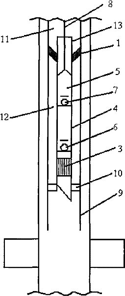
[0012] The present invention will be further described in detail below in conjunction with the embodiments: as shown in the accompanying drawings, the lower part of the sealer 1 is connected to the integrated suction pump 2, and the liquid inlet screen 3 is connected to the lower part of the integrated suction pump 2, and the sealer 1, The integrated suction pump 2 and the liquid inlet screen 3 form a liquid discharge device. The integrated suction pump 2 is composed of a pump barrel 4 and a plunger 5. There is a liquid inlet valve 6 at the lower part of the pump barrel and a liquid discharge valve 7 on the plunger. , the continuous wire rope 8 is connected with the integrated suction pump plunger. During the construction operation, the drainage device is continuously and quickly lowered to the predetermined position downhole by the continuous steel wire rope. The predetermined position is determined by the positioning ring 10 installed on the oil pipe 9. The sealer 1 isolates ...


PUM


Abstract

The invention discloses a quick fluid-discharge technology in the petroleum industry, a fluid-discharge device is quickly delivered downwards to a presetting location in the pit by a continuous steel wire rope, the fluid-discharge device is composed of a sealing device, an integrated sucking pump and a liquid inlet screening pipe, the integrated sucking pump is driven to move in a reciprocating way by the power which is supplied by the steel wire rope, thereby realizing the quick flowback of fluid in the pit. A construction operation method of continuous and quick back-flowing of the fluid in the pit to the ground is realized by the quick fluid-discharge technology, and the quick fluid-discharge technology has the characteristics of simple construction, fast speed, high efficiency and low operation cost. The quick fluid-discharge technology can be widely applied to the continuous and quick fluid-discharge of an oil (water) well.

Description

Technical field: [0001] The invention belongs to an oil (water) well drainage process, in particular to a rapid liquid drainage process, which is used in oil production wells in the petroleum industry to lift liquid continuously and rapidly. Background technique: [0002] In oilfield production, when implementing oil (water) well negative pressure perforation, acidification, plugging removal, fracturing and other measures, in order to reduce the secondary pollution of oil (water) layer, it is necessary to discharge the construction treatment fluid from downhole to the ground. At present, there are two main types of liquid drainage technologies commonly used: one is to insert tools such as pumps into the downhole tubing, and the well equipment drives the pumps to reciprocate up and down to drain the downhole liquid to the ground. Due to the limitation of the lowering depth, this technology has the problems of low efficiency, shallow lifting depth and incomplete drainage. The...

Claims


Application Information

Patent Timeline
Patent Type & Authority Applications(China)
IPC IPC(8): E21B43/00
Inventor 张卫张立忠王峰王立军张立胜高静
Owner 胜利油田东润科工贸有限责任公司
Why Eureka
Try Eureka