Ring body for suppressing propagation of earth pressure, its mounting structure, disc cutter and roller device

A technology of earth pressure and ring body, which is applied in the field of disc-shaped hob and roller device, and earth pressure propagation suppression ring body, can solve the problems of increasing production cost and achieve the effect of increasing rotation resistance

Active Publication Date: 2014-01-01
KOMATSU LTD +1
View PDF9 Cites 0 Cited by
  • Summary
  • Abstract
  • Description
  • Claims
  • Application Information

AI Technical Summary

Problems solved by technology

However, at this time, it is necessary to use a material with extremely high hardness on the sliding contact surface of the seal, and it is necessary to make the surface roughness of the sliding contact surface more precise (usually below 0.05S to 0.8S), which further increases the production cost.

Method used


Image

  • Ring body for suppressing propagation of earth pressure, its mounting structure, disc cutter and roller device
  • Ring body for suppressing propagation of earth pressure, its mounting structure, disc cutter and roller device
  • Ring body for suppressing propagation of earth pressure, its mounting structure, disc cutter and roller device

Examples


no. 1 approach

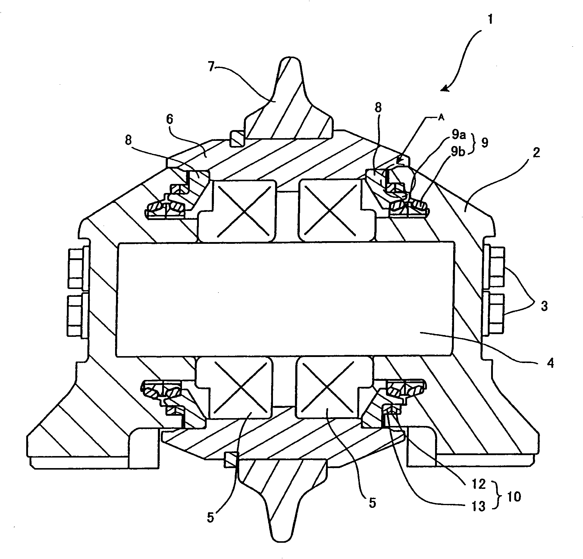
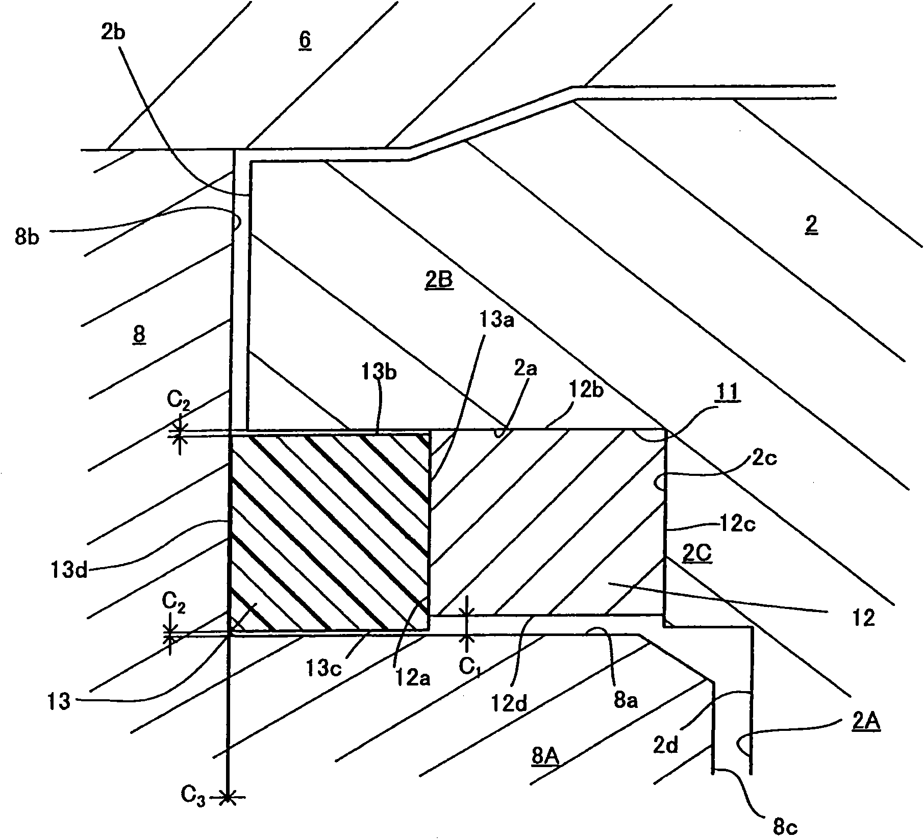
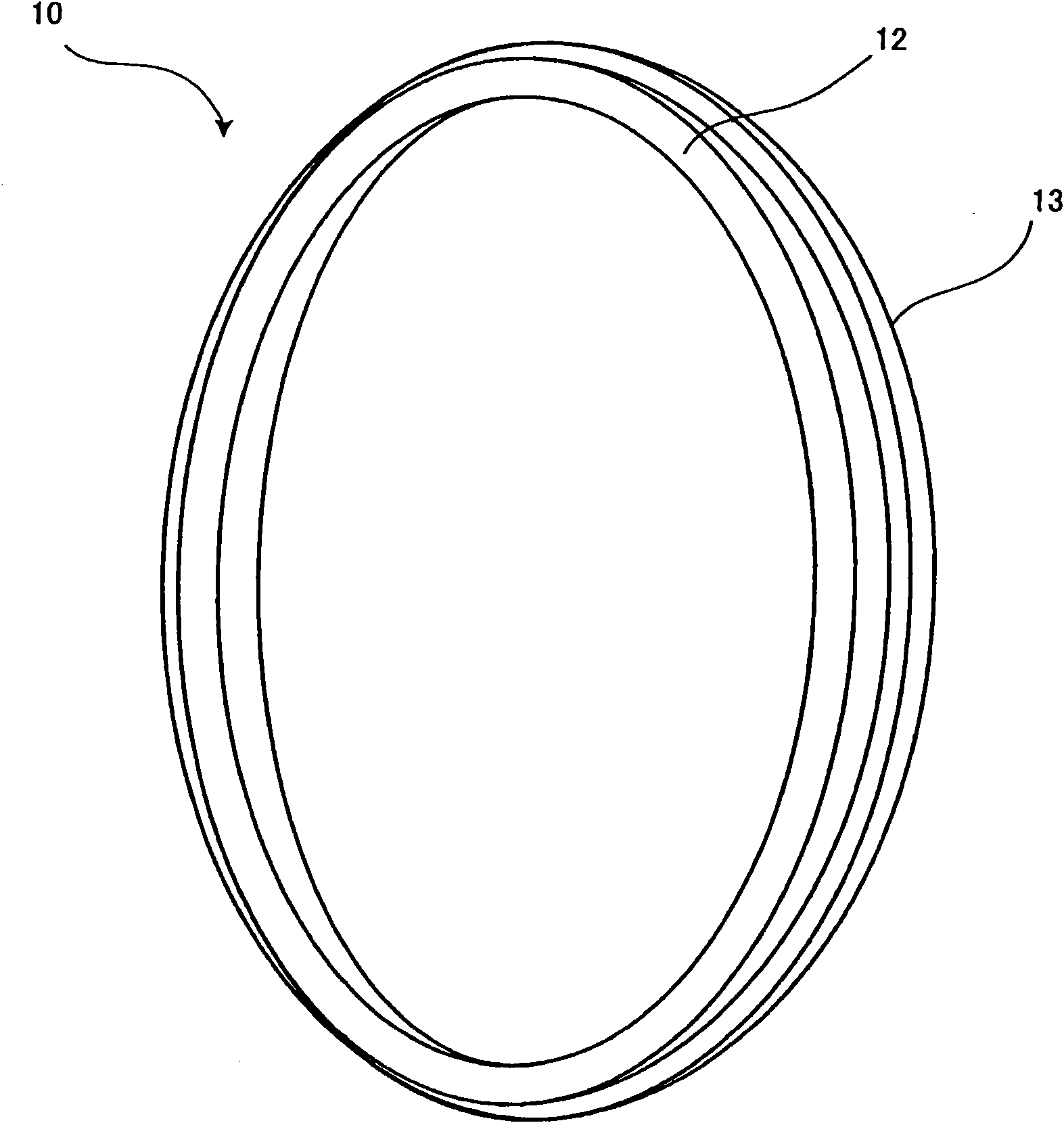
[0037] exist figure 1 shows a sectional view of a disc hob according to the first embodiment of the present invention, in figure 2 shown in figure 1 Enlarged view of part A. Moreover, in image 3 A perspective view of the ring body in this embodiment is shown in .

[0038] This embodiment shows an example applied to a disc hob mounted on a cutter head of a tunnel excavator. The disc hob 1 of the present embodiment includes a pair of holders 2, 2 attached to a not-shown cutter head, and a shaft 4 fixed to the holders 2, 2 with bolts 3. As shown in FIG. A hub 6 is rotatably supported by bearings 5 ​​and 5 on the outer periphery of the shaft 4 , and a cutter ring 7 is non-rotatably supported on the outer periphery of the hub 6 . Furthermore, it is also possible to integrally form the hub with the cutter ring.

[0039] Ring-shaped washers 8 , 8 are fitted into outer ends on the inner peripheral side of the hub 6 , and are fixed to the hub 6 in a non-rotatable and water-tigh...

no. 2 approach

[0051] exist Figure 5 , shows a cross-sectional view of a roller device according to a second embodiment of the present invention. This embodiment shows an example of a roller device applied to a construction machine such as a bulldozer.

[0052] The roller device 20 of the present embodiment includes: a bracket 21 provided on the vehicle body side so as to be non-rotatable; a shaft 22 supported by the bracket 21 so as to be non-rotatable; and a roller 24 supported by a bearing 23 on the shaft 22 In order to be rotatable, the roller device 20 is configured so that a crawler belt (not shown) is guided by the roller 24 . Between the bracket 21 and the roller 24 is installed a floating seal 25 for preventing the intrusion of earth and sand and preventing the leakage of oil filled around the shaft.

[0053] A labyrinth is formed on the outer peripheral side of the floating seal 25, and the ring body 10 of the present invention is attached to the labyrinth. The structure of the...


PUM


Abstract

PURPOSE: A ring body for suppressing the propagation of earth pressure, an installation structure thereof, a disc cutter, and a front wheel device are provided to suppress the propagation of earth pressure to a rotation sliding part arranged inside the ring body. CONSTITUTION: A ring body(10) for suppressing the propagation of earth pressure comprises a first ring part(12) and a second ring part(13). The first ring part is composed of an elastic body. The second ring part is fixed to the side surface of the first ring part, and is composed of rotatable metal. The surface roughness of the second ring part is more than 12.5S.

Description

technical field [0001] The present invention relates to an earth pressure propagation suppressing ring body for suppressing propagation of earth pressure to a rotary sliding part arranged inside a disc hob, a roller device, and the like, an installation structure thereof, and the earth pressure propagation suppressing ring body mounted thereon Disc hob and roller device. Background technique [0002] Generally, since the disc hob installed on the cutter head of the tunnel machine or the roller device installed on the bulldozer and other construction machinery are used in places where they are in contact with soil, sand, mud, water, etc., in order to prevent these soil, mud, Floating seals are installed on the shaft rotating parts of these devices to prevent the intrusion of water, etc., and to prevent the leakage of grease or oil filled inside. Moreover, in order to reduce the damage caused by the intrusion of earth and sand on the sealing surface of the floating seal, a la...

Claims


Application Information

Patent Timeline
Patent Type & Authority Patents(China)
IPC IPC(8): E21D9/11F16C33/72F16J15/34
CPCE21B10/28F16J15/3268F16J15/3284Y10S277/908E21B10/25
Inventor 森冈享一浅野浩德永知宏玉矢祐二
Owner KOMATSU LTD
Why Eureka
Try Eureka