
Calibration method, device and calibration phantomof geometric parameters in CT (computer tomography) system

A technology of geometric parameter and calibration method, applied in the field of geometric parameter calibration

Active Publication Date: 2010-06-23
SHENZHEN INST OF ADVANCED TECH
View PDF0 Cites 56 Cited by
  • Summary
  • Abstract
  • Description
  • Claims
  • Application Information

AI Technical Summary

Problems solved by technology

However, this solution can only calibrate the coordinates of the projection center point of the light source on the detector plane

Method used


Image

  • Calibration method, device and calibration phantomof geometric parameters in CT (computer tomography) system
  • Calibration method, device and calibration phantomof geometric parameters in CT (computer tomography) system
  • Calibration method, device and calibration phantomof geometric parameters in CT (computer tomography) system

Examples


Embodiment Construction

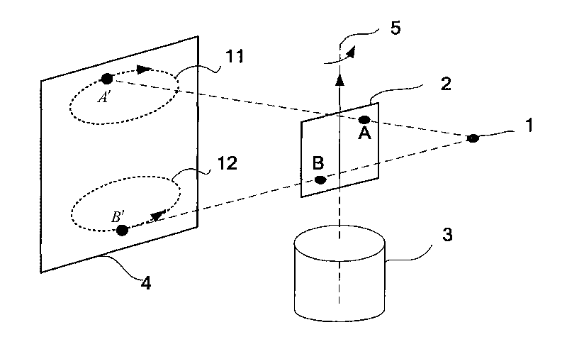
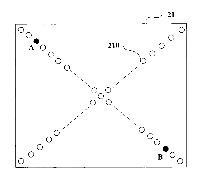
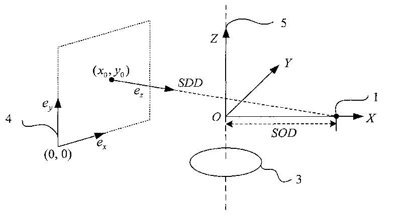
[0054] like figure 1 As shown, in one embodiment, the device for calibrating geometric parameters in the CT system includes a light source 1, a calibration phantom 2, a rotary table 3 and a detector 4, the rotary table 3 is located between the light source 1 and the detector 4, and the calibration phantom 2 is placed on the turntable 3. like figure 2 As shown, the calibration phantom 2 includes a calibration plate 21 and balls A and B mounted on the calibration plate 2 . The calibration plate 21 can be a polyethylene plastic plate, preferably, it is a plastic plate with a length and width of 50mm×50mm and a thickness of 2mm; the small ball A and the small ball B can be made of stainless steel balls, preferably, the small ball A and the small ball The diameters of B are all 0.8 mm.

[0055] In one embodiment, the calibration plate 21 is punched with a plurality of holes 210, preferably, a plurality of holes 210 are punched along the diagonal in the calibration plate 21, the...


PUM


Abstract

The invention provides calibration method, device and calibration phantom of the geometric parameters in a CT (computer tomography) system. In the method, the calibration phantom is placed on a rotary table positioned between a light source and a detector, the calibration phantom comprises a calibration plate, as well as a small ball A and a small ball B which are arranged on the calibration plate, the calibration phantom is rotated for a circle along with the rotary table, and a center point coordinates of projection images of the small ball A and the small ball B are collected by the detector; the coordinate of an intersection point of a projective point line of projection ellipses of the small ball A and the small ball B is calculated and obtained according to the center point coordinates of the projection images and and the center coordinates of the projection ellipses of the small balls, and the torsion angle of the detector, the distance from the light source to the detector, the projection center point coordinate of the light source on a imaging plane, the swinging angle of the detector and the distance from the light source to the rotary table can be calculated based on the coordinate of the intersection point of the projective point line and a elliptic equation. The invention can calibrate a plurality of parameters, and can sufficiently meet the requirement of subsequent CT image correction.

Description

【Technical field】 [0001] The present invention relates to geometric parameter calibration in CT system, and more particularly, to a calibration method, device and calibration phantom of geometric parameters in CT system. 【Background technique】 [0002] The basic principle of Computed Tomography (CT) is that X-rays pass through an object from all directions, and a computer program is used to analyze and measure all attenuated X-ray projections, reconstruct tomographic images, and obtain three-dimensional images. It can observe the internal structure of the object and obtain the internal information of the object without destroying the object. For decades, CT technology has been widely used in various fields such as medicine, pharmacy, materials science, industry, agriculture, engineering and archaeology. [0003] Micro-CT is a new type of equipment for high-resolution three-dimensional imaging using the principle of X-ray imaging. It can perform high-resolution three-dimensi...

Claims


Application Information

Patent Timeline
IPC IPC(8): G01B11/03G01B11/26G01B11/02A61B6/03
CPCA61B6/584
Inventor 胡战利郑海荣桂建保戎军艳邹晶李彦明席东星
Owner SHENZHEN INST OF ADVANCED TECH
Learn More