Eureka AIR delivers breakthrough ideas for toughest innovation challenges, trusted by R&D personnel around the world.

Power semiconductor module

A power semiconductor and integrated technology, which is applied in the direction of semiconductor devices, semiconductor/solid-state device manufacturing, electric solid-state devices, etc., can solve problems such as increasing assembly man-hours, reducing production efficiency, and hidden dangers

Inactive Publication Date: 2010-06-23
LSIS CO LTD
View PDF0 Cites 0 Cited by
  • Summary
  • Abstract
  • Description
  • Claims
  • Application Information

AI Technical Summary

Problems solved by technology

The above-mentioned wire connection structure makes the structure of the DBC more complex, and reduces production efficiency due to increased assembly man-hours, becoming a potential adverse hidden danger

Method used


Image

  • Power semiconductor module
  • Power semiconductor module
  • Power semiconductor module

Examples


Embodiment Construction

[0012] Below, the embodiments of the present invention will be described in detail with reference to the accompanying drawings. In the process, the size or shape of structural elements shown in the drawings will be exaggerated for clarity and convenience of description. In addition, the terms specifically defined in consideration of the structure and operation of the present invention may vary depending on the user's or application's intention or practice. The definitions of the above terms should be determined based on the contents of the entire specification.

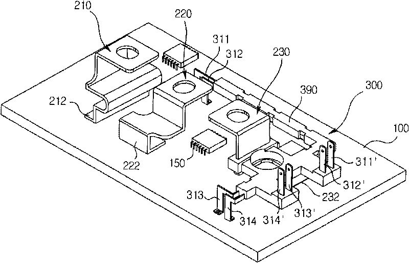
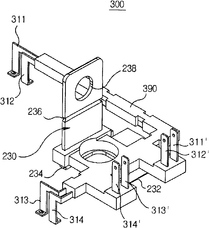
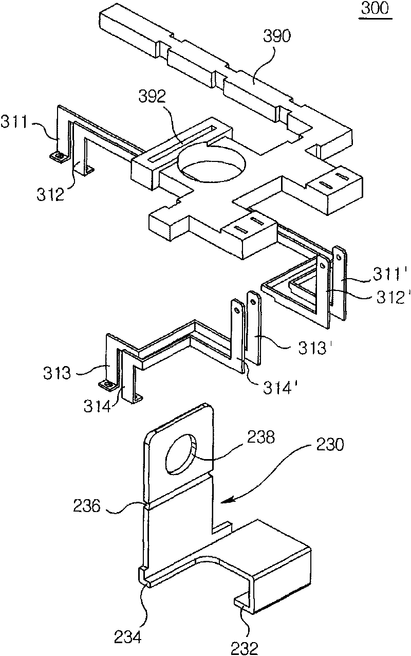
[0013] figure 1 It is a schematic structural diagram of the power semiconductor module of the present invention; figure 2 It is a schematic diagram of the appearance of the integrated terminal unit of the present invention; image 3 for figure 2 assembly diagram. The following will be combined Figure 1 to Figure 3 , the structure and function of the power semiconductor module of the present invention will be ...


PUM


Abstract

A power semiconductor module is disclosed, comprising: a substrate mounted with a power semiconductor device and formed with a pattern; and an integrated terminal unit integrally assembled with a power terminal for applying power to the substrate and a body in which a signal terminal for inputting a signal to or outputting the signal from the substrate is made of an insulated resin material, wherein the integrated terminal unit can be mounted to the substrate to allow the power terminal and the signal terminal to be simultaneously connected to the substrate.

Description

technical field [0001] The present invention relates to a power semiconductor module, which is a component that integrates power supply terminals for supplying power and signal terminals for input / output signals, and can be mounted on a substrate. Background technique [0002] Power semiconductor modules are used in inverters, converters and uninterruptible power supplies, etc., and refer to power modules used for motor control, switching and power supply. [0003] In general, when manufacturing a power semiconductor module composed of IGBT, power MOSFET, or bipolar transistor, the bonding process of each material is as follows: bonding transistor elements and diode elements to a DBC (direct bonded copper: direct bonded copper) substrate After connecting with wires, the power supply terminals and signal terminals connected to the outside are bonded to the above-mentioned board. [0004] Here, the power terminals and signal terminals in the prior art are generally independen...

Claims


Application Information

Patent Timeline
IPC IPC(8): H01L23/48H01L23/12H01L23/28
CPCH01L2924/0002H01L23/49811H01L23/3735H01L2924/13091H01L2924/13055H01L25/072H01L2924/00H01L21/56H01L23/48
Inventor 李秉昊
Owner LSIS CO LTD
Why Eureka
Eureka Blog
Learn More