Light-emitting component

A technology for light-emitting components and transparent conductive oxidation, which is applied to electrical components, semiconductor devices, circuits, etc., and can solve the problems of the reduction of the luminous efficiency of the light-emitting component 100 and the decrease of the brightness of the light-emitting component 100.

Active Publication Date: 2010-06-23
EPISTAR CORP
View PDF0 Cites 5 Cited by
  • Summary
  • Abstract
  • Description
  • Claims
  • Application Information

AI Technical Summary

Problems solved by technology

[0005] However, in the manufacturing process of the above-mentioned known light-emitting component 100, the high-temperature process easily causes the ohmic contact layer 15 to react with the low-refractive index layer 142 in the omni-directional reflective layer 14, resulting in a decrease in the brightness of the light

Method used


Image

  • Light-emitting component
  • Light-emitting component
  • Light-emitting component

Examples


Embodiment Construction

[0038] Embodiments of the present invention are described below with reference to the accompanying drawings.

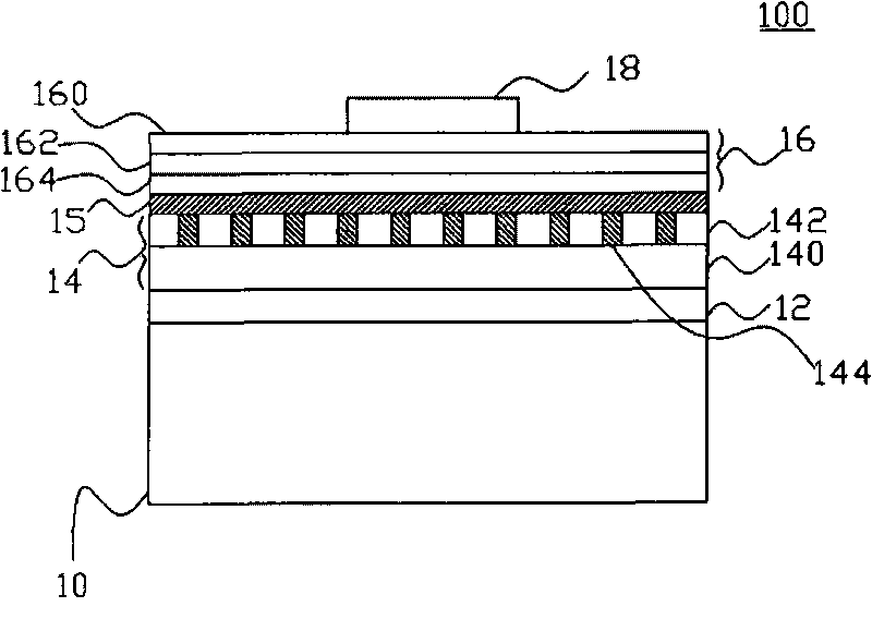
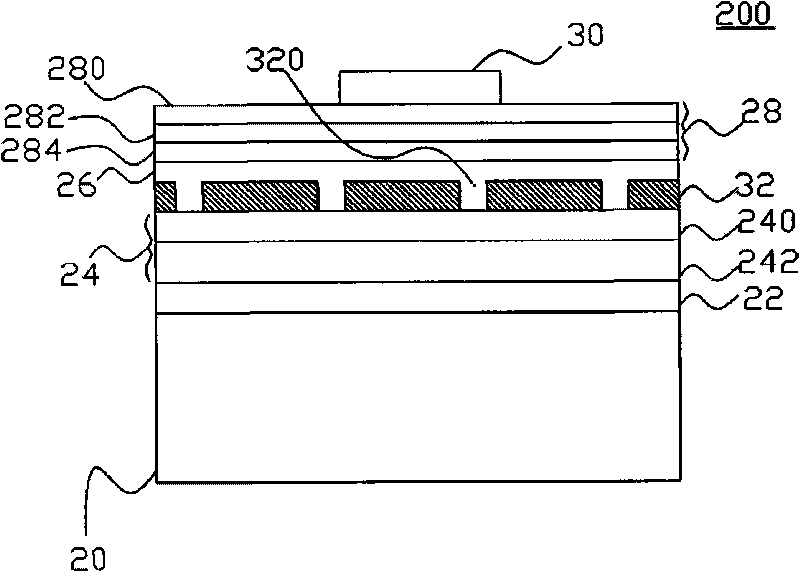
[0039] figure 2 It is a structural schematic diagram of an embodiment of the present invention, such as figure 2 As shown, the light-emitting component 200 includes a conductive substrate 20, an adhesive layer 22 disposed on the conductive substrate 20, an omni-directional reflective layer 24 (omni-directional reflector, ODR) located on the adhesive layer 22, and an omni-directional reflector located on the aforementioned omni-directional reflective layer 24. The first transparent conductive oxide layer 26, the light emitting stack 28 disposed on the first transparent conductive oxide layer 26; and the electrode 30 located on the light emitting stack 28; wherein, the omnidirectional reflective layer 24 and the first transparent conductive The oxide layer 26 further includes a transparent insulating barrier layer 32 , and the omnidirectional reflective layer 24 furt...


PUM


Abstract

The invention discloses a light-emitting component which at least comprises a light-emitting laminated layer, a first transparent conductive oxidation layer positioned under the light-emitting laminated layer, a transparent insulating layer positioned under the first transparent conductive oxidation layer, a second transparent conductive oxidation layer positioned under the transparent insulating layer, and a metallic reflection layer positioned under the second transparent conductive oxidation layer, wherein an omni-directional reflector (ODR) layer is formed by the metallic reflection layer and the second transparent conductive oxidation layer, and ohmic contact is formed between the first transparent conductive oxidation layer and the light-emitting laminated layer, so that the light-emitting efficiency of the light-emitting component can be improved.

Description

technical field [0001] The present invention relates to a light-emitting component, in particular to a light-emitting component structure with an insulating barrier layer (dielectric barrier layer) located between a first transparent conductive oxide layer and a second transparent conductive oxide layer. Background technique [0002] The light-emitting diode (light-emitting diode, LED) uses the energy difference between n-type semiconductors and p-type semiconductors to release energy in the form of light. This light-emitting principle is different from that of incandescent lamps. Principle, so light-emitting diodes are called cold light sources. In addition, light-emitting diodes have the advantages of high durability, long life, light weight, and low power consumption. Therefore, today's lighting market places high hopes on light-emitting diodes and regards them as a new generation of lighting tools. [0003] figure 1 It is a schematic diagram of the structure of a known...

Claims


Application Information

Patent Timeline
IPC IPC(8): H01L33/00
Inventor 林锦源杨雅兰
Owner EPISTAR CORP
Why Eureka
Try Eureka