
Case structure of outer rotor motor and rotor component made by case

一种外转子电机、壳体结构的技术,应用在磁路转动零部件、带有静止电枢和旋转磁体的同步电动机、电气元件等方向,能够解决加工麻烦、制造成本高、消耗能量等问题,达到生产加工容易、散热效果好、制造成本低的效果

Active Publication Date: 2010-06-23
ZHONGSHAN BROAD OCEAN
View PDF0 Cites 23 Cited by
  • Summary
  • Abstract
  • Description
  • Claims
  • Application Information

AI Technical Summary

Problems solved by technology

[0002] The shell structure of the traditional outer rotor motor is generally made of all metal parts, including the ring-shaped outer wall and the end cover at the bottom of the side wall, forming a cavity in the middle, opening the top to form an opening, and installing a magnetizer on the ring-shaped outer wall Shell, magnetic tiles are installed in the magnetic shell, the whole shell structure is relatively bulky, the cost is high, and the effective energy is consumed. On the end cover, a number of grooves are generally punched out by a punch to dissipate heat. The heat dissipation effect is poor, and it can only be rotated forward or Air intake and heat dissipation can only be achieved by reversing, which is troublesome to process and high in manufacturing cost

Method used


Image

  • Case structure of outer rotor motor and rotor component made by case
  • Case structure of outer rotor motor and rotor component made by case
  • Case structure of outer rotor motor and rotor component made by case

Examples


Embodiment Construction

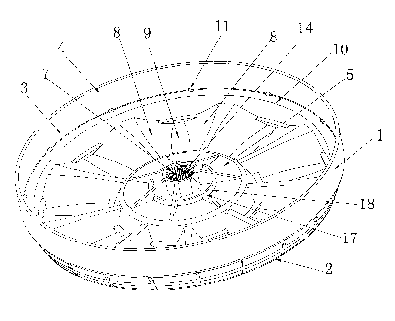
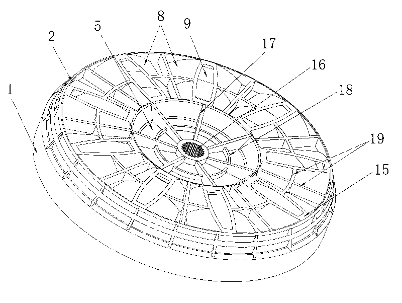
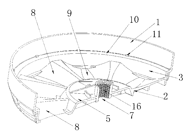
[0029] Such as Figure 1 to Figure 4 As shown, a housing structure of an outer rotor motor includes an annular outer wall 1 and an end cover 2 located at the bottom of the outer wall 1 , a cavity 3 is formed in the middle, an opening 4 is formed at the top, and a connection is formed at the center of the end cover 2 Seat 5, the center of the coupling seat 5 is provided with a keyway 7 connected to the motor drive shaft, the coupling seat 5 and the annular outer wall 1 are connected by a number of fan blades 8, and an air inlet 9 is formed between two adjacent fan blades 8 . The thickness in the middle of the fan blade 8 is the largest, and the thickness of the air inlets 9 on both sides decreases gradually from the middle, so that axial airflow can be generated when the housing rotates forward or reversed, and heat dissipation to the motor winding is formed. The middle part of the outer wall 1 forms an annular step 10, the surface of the step 10 protrudes several small bosses...


PUM


Abstract

The invention provides a case structure of an outer rotor motor, which comprises an annular outer side wall (1) and an end cover (2), wherein the end cover (2) is positioned at the bottom end of the outer side wall (1), a cavity (3) is formed in the middle of the case structure, the top of the case structure is open for forming an opening (4), a connection seat (5) is formed in the center of the end cover (2), the center of the connection seat (5) is provided with a key groove (7) connected with a transmission shaft of the motor, the connection seat (5) and the annular outer side wall (1) are connected through a plurality of blades (8), and air inlet openings (9) are formed between two adjacent blades (8). The case structure is provided with a plurality of blades, the air inlet openings are formed between the two adjacent blades, when the case rotates, the blades generate the air flow blowing in the axial direction for forming the heat radiation on a motor winding, and the heat radiation effect is good. The blades can generate the air flow blowing both in positive rotation or reverse rotation, and the heat radiation on the motor winding can be formed. The injection molding case structure has the certain buffer effect, and the vibration can be reduced.

Description

technical field [0001] The invention relates to a casing structure of an outer rotor motor and a rotor component manufactured by using the casing. Background technique [0002] The shell structure of the traditional external rotor motor is generally made of all metal parts, including the annular outer wall and the end cover at the bottom of the side wall. A cavity is formed in the middle, and the top is opened to form an opening. The magnetic guide is installed on the annular outer wall. Shell, magnetic tiles are installed in the magnetic shell, the whole shell structure is relatively bulky, the cost is high, and the effective energy is consumed. On the end cover, a number of grooves are generally punched out by a punch to dissipate heat. The heat dissipation effect is poor, and it can only be rotated forward or Wind can enter and dissipate heat only by reversing, which is cumbersome to process and high in manufacturing cost. Contents of the invention [0003] The object ...

Claims


Application Information

Patent Timeline
Patent Type & Authority Applications(China)
IPC IPC(8): H02K5/04H02K9/06H02K1/27H02K1/28
CPCH02K15/12H02K7/003H02K1/32H02K1/2786H02K1/30H02K9/06H02K1/2791H02K9/04H02K21/22
Inventor 张旭
Owner ZHONGSHAN BROAD OCEAN
Learn More