Switch power supply

A switching power supply, switching current technology, applied in the energy industry, electrical components, regulating electrical variables, etc., can solve the problems of increasing the area of ​​the circuit board and the space of the components, and achieve the reduction of the overall weight, the improvement of the power factor, and the reduction of the volume. Effect

Inactive Publication Date: 2010-06-23
HOLTEK SEMICON
View PDF0 Cites 7 Cited by
  • Summary
  • Abstract
  • Description
  • Claims
  • Application Information

AI Technical Summary

Problems solved by technology

This common approach to complex system design adds unnecessarily to board area and component space, regardless of cost

Method used


Image

  • Switch power supply
  • Switch power supply
  • Switch power supply

Examples


Embodiment Construction

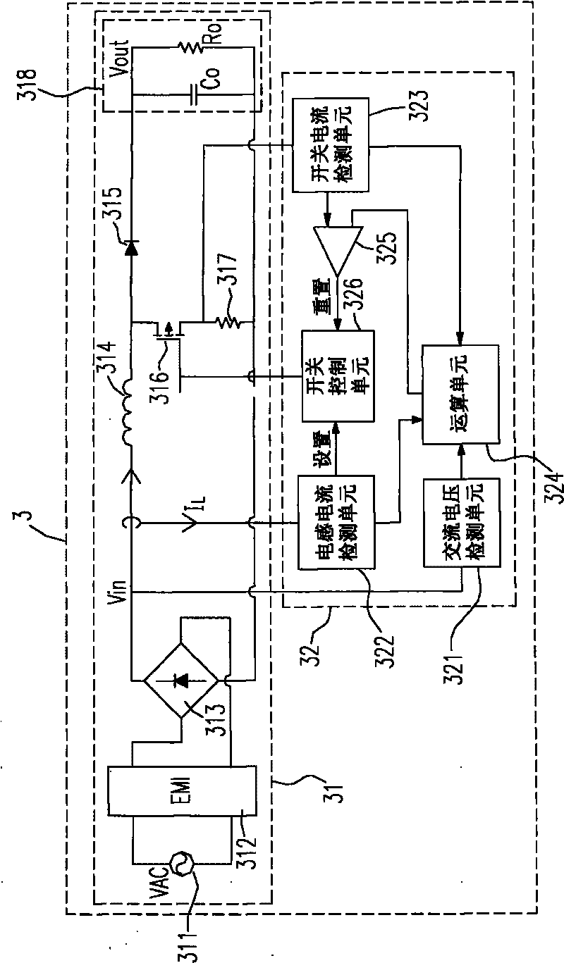
[0034] See image 3 , which shows the circuit block diagram of the first embodiment of the switching power supply proposed by the present invention. The PFC switching power supply 3 includes a boost converter 31 and a PFC controller 32 . The boost converter 31 includes a mains input stage 311 , an EMI protection circuit 312 , a rectifier 313 , an inductor 314 , a diode 315 , a switch 316 , a resistor 317 and an output stage 318 . The PFC controller 32 includes an AC voltage detection unit 321 , an inductor current detection unit 322 , a switch current detection unit 323 , an arithmetic unit 324 , a comparator 325 and a switch control unit 326 .

[0035]Under typical operating conditions, the mains input stage 311 receives the AC voltage VAC, which is stepped down by the EMI protection circuit 312 and rectified by the rectifier 313 to output the input voltage Vin. At this time, it is coupled to the AC voltage detection of the boost converter 31 The unit 321 detects the input ...


PUM


Abstract

The invention discloses a switch power supply of a power factor correction controller, comprising a boosting converter, a current detection unit, an operational unit and a switch control unit; the current detection unit is used for detecting or driving current to pass through an energy transferring device, and the energy transferring device is composed of a diode or a switch commonly; the current detection unit is used for detecting inductive current or switch current. Under the condition of no-load direct detection, the optical switch breakover time is operated by an arithmetic element according to the current detection unit, or the switch can be powered off at any time; in the switch power supply of the invention, the circuit needed to detect load-end voltage in the prior art is removed, the whole weight is reduced and the system cost is reduced; in addition, the power factor of the system can be improved by detecting the current transferring way of the energy transferring, thereby being different from the prior art.

Description

technical field [0001] The present invention relates to switched mode power supplies (SMPS), and more particularly to power factor corrected (PFC) switched mode power supplies. Background technique [0002] Although there are many types of switch-mode power supplies and there are too many to enumerate, but looking at the previous related known technologies, the stable method of controlling the output voltage of the power supply is nothing more than intercepting a signal from the output load terminal to communicate with the internal The signal comparison is moderately adjusted by controlling the internal circuit to maintain the stability of the voltage output and provide low-power electronic consumer devices with stable power requirements. [0003] However, although these technologies can provide a stable output voltage source, they must pass through the detection circuit at the load end, which not only increases the production cost of this type of power supply, but also occu...

Claims


Application Information

Patent Timeline
Patent Type & Authority Applications(China)
IPC IPC(8): H02M3/10H02M3/156H02M1/42
CPCY02B70/126Y02B70/10Y02P80/10
Inventor 刘文坤蓝义孟简铭宏
Owner HOLTEK SEMICON
Why Eureka
Try Eureka