Control circuit and method for flyback converter

A technology of control circuit and control method, which is applied in the direction of control/regulation system, conversion equipment with intermediate conversion to AC, instruments, etc., to achieve the effect of reducing switching loss, reducing switching times, and reducing ripples

Inactive Publication Date: 2010-06-23
RICHTEK TECH
View PDF4 Cites 13 Cited by
  • Summary
  • Abstract
  • Description
  • Claims
  • Application Information

AI Technical Summary

Problems solved by technology

[0008] Therefore there is above-mentioned inconvenience and problem in known power converter

Method used


Image

  • Control circuit and method for flyback converter
  • Control circuit and method for flyback converter
  • Control circuit and method for flyback converter

Examples


Embodiment Construction

[0091] The present invention will be further described below in conjunction with embodiment and accompanying drawing.

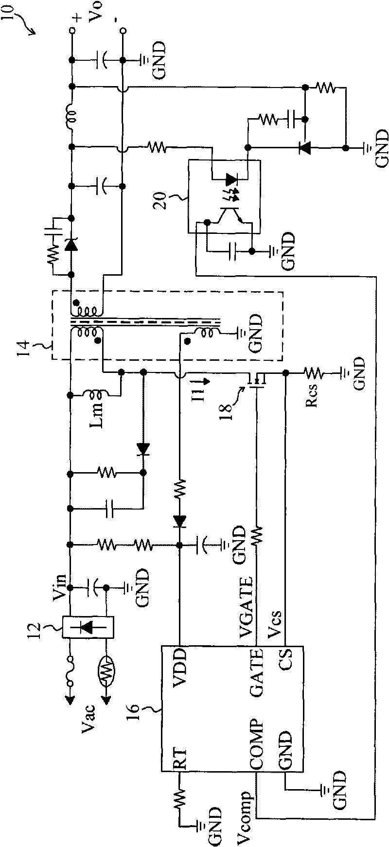
[0092] now please refer to figure 1 , those skilled in the art know the amount of change of the current sensing signal Vcs within a preset time Δton

[0093] ΔVcs=(Vin / Lm)×Δton×Rcs Formula 2

[0094] It can be seen from formula 2 that the variation ΔVcs of the current sensing signal Vcs is proportional to the input voltage Vin, so it is only necessary to multiply the variation ΔVcs of the current sensing signal Vcs by an appropriate coefficient

[0095] K=Tp / Δton Formula 3

[0096] can eliminate the effect caused by the propagation delay in Equation 1 (Vin / Lm)×Tp, so that figure 1 The peak value of the current I1 on the primary side of the middle transformer 14 is almost the same regardless of whether the input voltage is high or low, thereby reducing noise. Figure 7 The first embodiment of the control circuit of the flyback power converter of the presen...


PUM


Abstract

The invention relates to a control circuit of a flyback converter. The flyback converter comprises a transformer and a power switch connected with the primary side of the transformer. The control circuit switches the power switch to convert an input voltage of the transformer into an output voltage. The control circuit comprises a sampling and sustain circuit, a compensation circuit and a pulse width modulation circuit and is characterized in that the sampling and sustain circuit is used for obtaining the variable quantity of a sensing signal in the predetermined time, and the sensing signal is the function of the input voltage; the compensation circuit compensates a first feedback signal with the variable quantity of a inductance current signal to generate a second feedback signal changing with the input voltage, and the first feedback signal is the function of the output voltage; and the pulse width modulation circuit is used for determining the working time of the power switch according to the sensing signal and the second feedback signal.

Description

technical field [0001] The invention relates to a flyback converter, in particular to a control circuit and method of the flyback converter. Background technique [0002] All electronic devices need power to operate. In power supplies, switching power converters are widely used because they have better performance and can provide proper output regulation. figure 1 A known current mode flyback power converter 10 is shown, wherein a rectifier 12 rectifies an AC voltage Vac to generate a DC input voltage Vin, and a sense resistor Rcs is connected in series with a power switch 18 for detecting a current I1 passing through the power switch 18 to After obtaining the sensing signal Vcs, the control circuit 16 generates a control signal VGATE according to the sensing signal Vcs and the feedback signal Vcomp to switch the power switch 18 so that the transformer 14 converts the input voltage Vin into an output voltage Vo, and an opto-coupler (opto-coupler) 20 The detected output volt...

Claims


Application Information

Patent Timeline
Patent Type & Authority Applications(China)
IPC IPC(8): H02M3/28G05F1/10
Inventor 黄培伦陈佑民林梓诚
Owner RICHTEK TECH
Why Eureka
Try Eureka