Method for electrically controlling hydraulic differential of centrifuge

An electrical control and centrifuge technology, applied in centrifuges and other directions, can solve the problems of inability to produce high-precision mechanical automatic control valves, high prices, and inability to be widely used, and achieve simple structure, reduce production costs, and speed up discharge. Effect

Inactive Publication Date: 2010-06-30
SHANGHAI CENTRIFUGE INST
View PDF0 Cites 10 Cited by
  • Summary
  • Abstract
  • Description
  • Claims
  • Application Information

AI Technical Summary

Problems solved by technology

[0003] To realize the above-mentioned differential control function, foreign hydraulic differential controllers are implemented with high-precision mechanical automatic control valves and variable hydraulic pumps. Domestically, similar high-precision mechanical automatic control valves cannot be produced, and there are only two companies in Switzerland and Germany abroad. able to produce, very expensive
Unable to be widely used in domestic centrifuges

Method used


Image

  • Method for electrically controlling hydraulic differential of centrifuge
  • Method for electrically controlling hydraulic differential of centrifuge
  • Method for electrically controlling hydraulic differential of centrifuge

Examples


Embodiment Construction

[0023] The present invention will be further described below in conjunction with accompanying drawing:

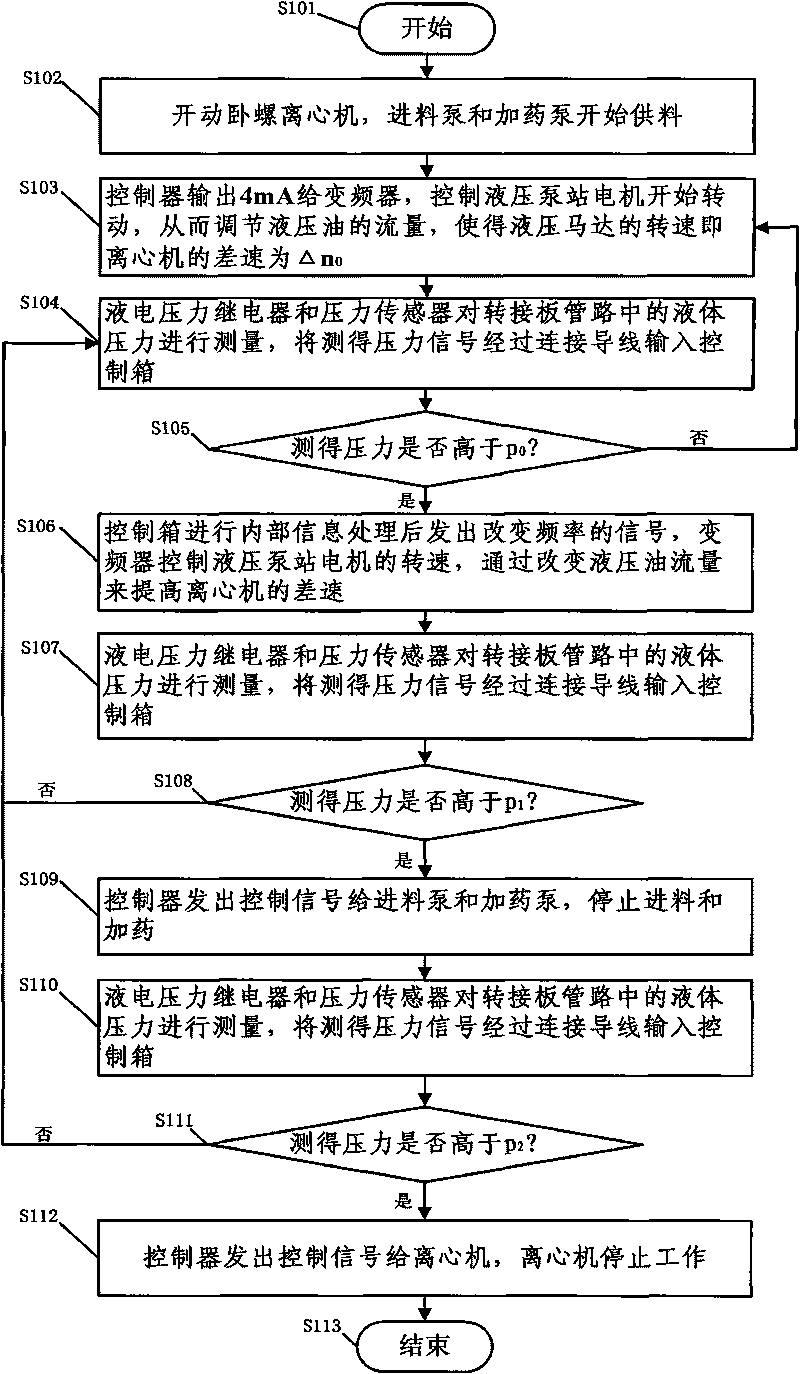
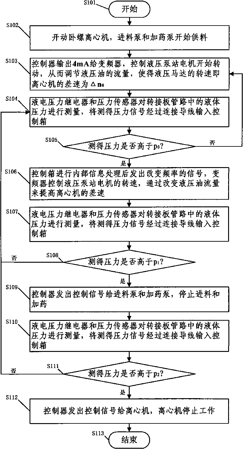
[0024] figure 1 It is a flow chart of the electric control method for the hydraulic differential speed of the centrifuge of the present invention. The process starts at step 101 . Then in step 102, the decanter centrifuge is started, and the feed pump and the dosing pump start to supply materials.

[0025] In step 103, the controller outputs 4mA to the frequency converter to control the motor of the hydraulic pump station to start rotating, thereby adjusting the flow of hydraulic oil so that the speed of the hydraulic motor, that is, the differential speed of the centrifuge, is Δn 0 .

[0026] In step 104, the liquid-electric pressure relay and the pressure sensor measure the liquid pressure in the pipeline of the adapter plate, and input the measured pressure signal into the control box through the connecting wire.

[0027] In step 105, the above-mentioned measured pre...


PUM


Abstract

The invention relates to a method for electrically controlling the hydraulic differential of a centrifuge, in particular to a method for electrically controlling the hydraulic differential of a horizontal decanter centrifuge for sludge dewatering. The method realizes the electrical control of the hydraulic differential by using a programmable intelligent instrument as a controller, wherein three pressure values p0, p1 and p2 are set on the controller; when the pressure is less than p0, the differential of the centrifuge remains delta n0 unchanged; when the pressure is greater than p0, the differential is increased along with the increment of the pressure; when the pressure is greater than p1, a feed pump and a dosing pump are stopped; and when the pressure is greater than p2, the centrifuge is stopped. Through the method, a liquid pressure changing signal in a pipeline of an adapter plate can be fed back to the controller in time; according to the change of the pressure, the flow of a hydraulic system can be adjusted proportionally in real time; the structure is simple and the usage is convenient; and at the same time, the production cost of the hydraulic differential controller of the horizontal decanter centrifuge is greatly reduced, which is one third of the price of the similar foreign products.

Description

technical field [0001] The invention relates to a hydraulic differential electric control method, in particular to a hydraulic differential electric control method for a dewatering decanter centrifuge. Background technique [0002] At present, the differential control of the decanter centrifuge used for sludge dewatering generally includes hydraulic control, double frequency conversion control differential, mechanical differential, and electric eddy current control differential. Because the hydraulic differential has small differential speed and low energy It is the first choice for differential speed control in decanter centrifuges due to the advantages of high energy consumption and high dryness. In the prior art, the differential speed is generated by the output shaft of the hydraulic motor driven by the hydraulic oil in the hydraulic system to drive the spiral rotation of the centrifuge. The differential speed provides the separation of the solid phase and the liquid pha...

Claims


Application Information

Patent Timeline
Patent Type & Authority Applications(China)
IPC IPC(8): B04B13/00
Inventor 陆中华韦黎明陆炯
Owner SHANGHAI CENTRIFUGE INST
Why Eureka
Try Eureka