

Digitally-controlled wire drawing machine and control method thereof
A technology of wire drawing machine and main motor, which is applied in the direction of manufacturing tools, metal processing, metal processing equipment, etc., and can solve problems such as the need to change the counterweight or cylinder air pressure, unfavorable operation and management, and wire scratches
- Summary
- Abstract
- Description
- Claims
- Application Information
AI Technical Summary
Problems solved by technology
Method used
Image

Examples
Embodiment 1
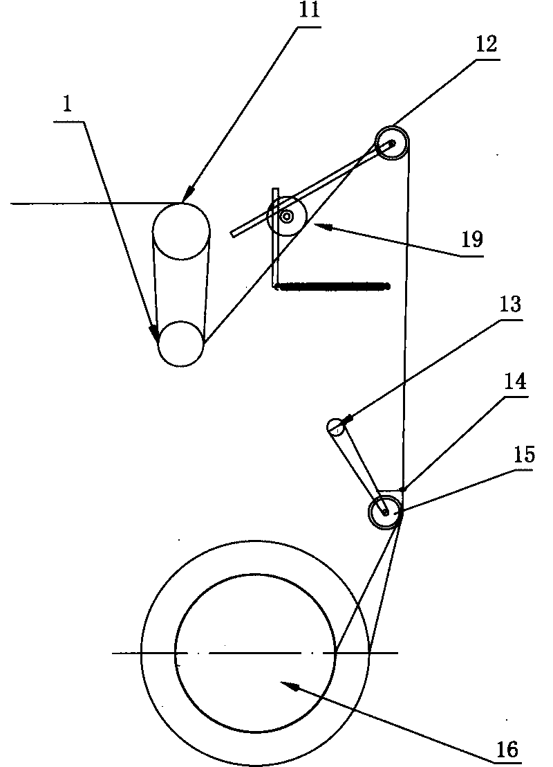
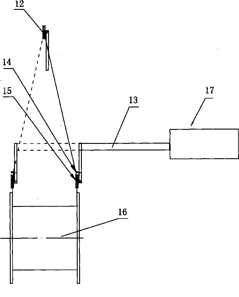
[0068] Embodiment one, such as Figure 5 , Figure 6 shown, with figure 1 and figure 2 A single frequency conversion wire drawing machine of the prior art shown, and image 3 and Figure 4 Compared with the structure of the double-frequency conversion wire drawing machine shown in the prior art, the speed measuring device of the fixed speed wheel 11 is canceled in the present invention. The traditional single frequency conversion wire drawing machine needs to measure the speed of the fixed speed wheel 11 to obtain the slip, and the double frequency conversion wire drawing machine needs to measure the speed of the fixed speed wheel 11 to obtain the production line speed. The present invention does not need to use the slip to control, and the speed measurement of the line dividing guide wheel 1 can obtain the line speed more accurately, so the speed measurement of the fixed speed wheel 11 is not required. Even if the slip is to be displayed as a reference, it can be estima...
Embodiment 2
[0075] Embodiment two, such as Figure 9 As shown, the difference between the second embodiment and the first embodiment is that the intermediate guide wheel 12 is a fixed guide wheel fixedly installed. Although the buffer guide wheel of the first embodiment changes suddenly in tension, the PLC control does not respond in time. When coming over, it can play a buffering effect, but if the control software is designed well or the PLC response is fast enough, it is also possible to replace the buffer guide wheel with a fixed guide wheel, and cancel the elastic fork device 19, which can simplify the structure.
Embodiment 3
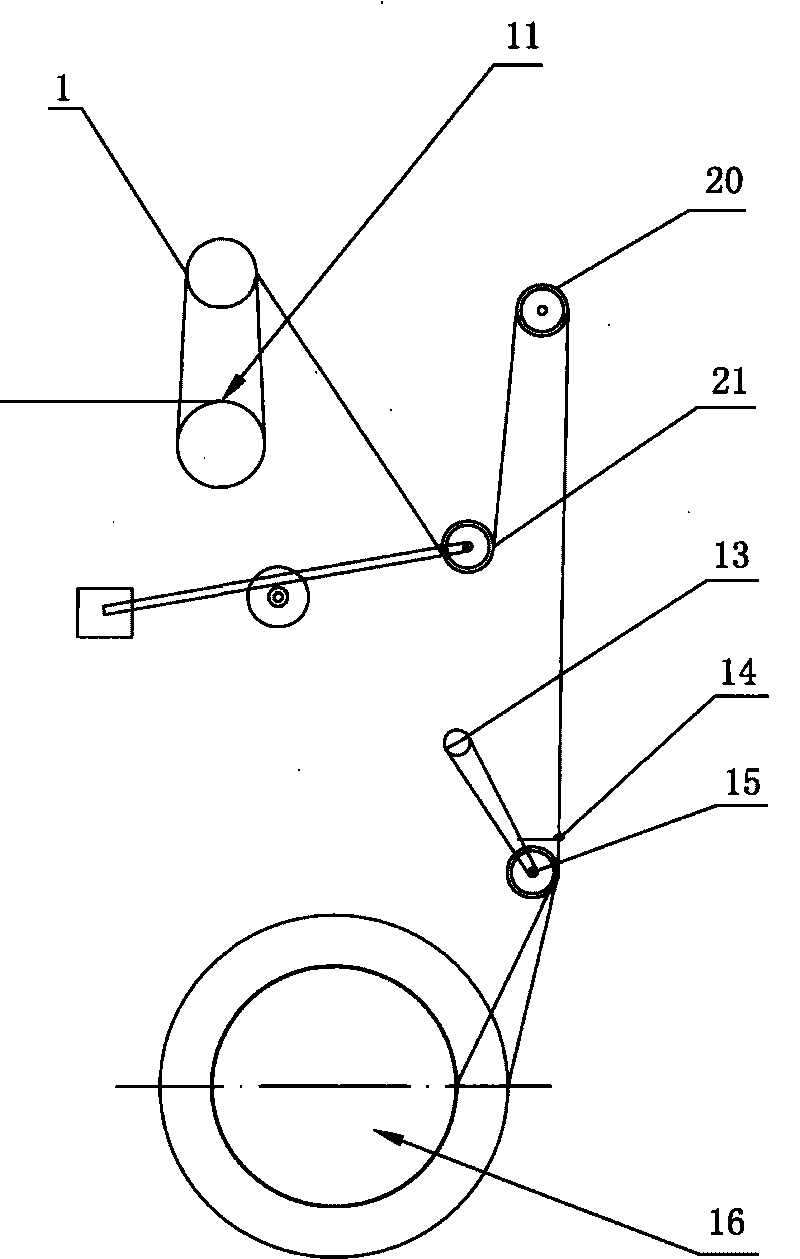
[0076] Embodiment three, such as Figure 10 As shown, the difference between the third embodiment and the first embodiment is that the line dividing guide wheel 1 is located below the fixed speed wheel 11, and the intermediate guide wheel 12 is a fixed guide wheel fixedly installed. This structure can save the directional guide wheel 10, but the disadvantage is that the included angle of the line from the branch guide wheel 1 to the middle guide wheel 12 is not fixed, and the corresponding relationship between the induction value of the branch guide wheel tension sensor 32 and the wire tension is not correct. Strict, but the impact is not very large. In addition, the self-weight direction of the thread-dividing guide wheel 1 is different from the tension direction, which may cause inaccurate measurement, but this problem can also be solved by calibration. This structure can be used as the most concise and basic structure of a numerically controlled wire drawing machine descri...
PUM
| Property | Measurement | Unit |
|---|---|---|
| Bottom length | aaaaa | aaaaa |
Abstract
Description
Claims
Application Information