Guide flow type thermal evaporation depositing device

A deposition device and thermal evaporation technology, applied in the field of thermal evaporation thin film preparation, can solve problems such as inapplicable applications

Inactive Publication Date: 2010-06-30
LASER FUSION RES CENT CHINA ACAD OF ENG PHYSICS
View PDF0 Cites 1 Cited by
  • Summary
  • Abstract
  • Description
  • Claims
  • Application Information

AI Technical Summary

Problems solved by technology

However, thermal evaporation is usually carried out by steam deposition from the bottom to the top, which is not suitable for some applications that require steam to be deposited from the top to the bottom

Method used


Image

  • Guide flow type thermal evaporation depositing device
  • Guide flow type thermal evaporation depositing device
  • Guide flow type thermal evaporation depositing device

Examples


Embodiment Construction

[0027] The present invention will be further described below in conjunction with accompanying drawing

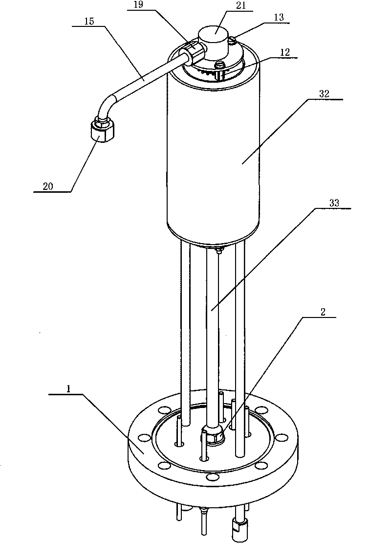
[0028] figure 1 It is a schematic diagram of the overall appearance of the diversion type thermal evaporation deposition device of the present invention. In the figure, the heating furnace 32 is fixedly arranged on the base flange 1 through the central axis 33, and the draft tube base 21 arranged on the top of the heating furnace 32 is connected through the connecting nut 19 is fixedly connected with the guide tube 15, and the top end of the guide tube 15 is provided with a nozzle cap 20.

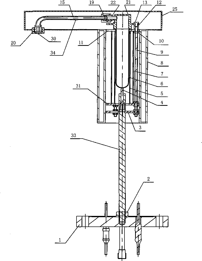
[0029] Figure 2-6 Among them, a diversion type thermal evaporation deposition device of the present invention includes a heating furnace 32, a draft tube 15 and a draft tube heating cover 25; the heating furnace 32 takes the central axis 33 as the center, and passes through the The heating wire frame 5 that is set, the inner insulation cylinder 7 and the outer insulation cylinder 8 con...


PUM


Abstract

The invention discloses a guide flow type thermal evaporation depositing device comprising a heating furnace, a guide flow pipe and a guide flow pipe heating cover. The heating furnace consist of a heating strip frame, an internal insulating cylinder and an external insulating cylinder; an evaporation boat is arranged in the heating strip frame; a central shaft is connected below a heating strip support seat in the heating furnace; the heating furnace is fixedly connected with a base flange through the central shaft; the guide flow pipe is in sealing connection with an evaporation opening of the evaporation boat; and the guide flow pipe is arranged in the guide flow heating cover. When materials in the evaporation boat are heated and evaporated, steam flows outward along the guide flow pipe as a result of the inside and outside pressure difference. Steam can be ejected from top to bottom due to the guiding function of the guide flow pipe. The device can realize chemical vapour phase deposition of two or more materials through two or more combinational arrangement, thereby solving the problem of thermal evaporation vapour phase deposition where samples need to be fixed at the lower part. The device ensures more centralized steam stream and can obtain higher deposition rate.

Description

technical field [0001] The invention belongs to the field of thermal evaporation thin film preparation, and in particular relates to a diversion type thermal evaporation deposition device used for thermal evaporation deposition of thin films. Background technique [0002] Thermal evaporation is one of the most basic and commonly used methods for thin film preparation. Because of its high deposition rate and high film quality, it is widely used in the field of thin film preparation. However, thermal evaporation is usually carried out by steam deposition from the bottom to the top, which is not suitable for some applications that require steam to be deposited from the top to the bottom. Contents of the invention [0003] In the prior art, thermal evaporation is not suitable for application fields where steam is deposited from above to below. The present invention provides a flow-conducting thermal evaporation deposition device, which is suitable for thermal evaporation vapo...

Claims


Application Information

Patent Timeline
IPC IPC(8): C23C14/24
Inventor 张占文黄勇漆小波李波刘一扬陈素芬魏胜
Owner LASER FUSION RES CENT CHINA ACAD OF ENG PHYSICS
Why Eureka
Try Eureka