
Bionic leg system for machine cat type railway bridge erecting machine

A technology of bridge erecting machine and robot cat, which is applied in the field of bionic outrigger system, to achieve the effect of saving auxiliary tools and large equipment, reducing preparation work, and speeding up the construction progress of beam erection

Active Publication Date: 2010-06-30
ZHENGZHOU NEW DAFANG HEAVY IND & TECH
View PDF0 Cites 9 Cited by
  • Summary
  • Abstract
  • Description
  • Claims
  • Application Information

AI Technical Summary

Problems solved by technology

[0003] The purpose of the present invention is to provide a bionic outrigger for a robot cat type railway bridge erecting machine in order to solve the problem that the railway bridge erecting machine can smoothly pass through the tunnel and recover quickly without the assistance of any external lifting machinery equipment in the form of a real complete machine system

Method used


Image

  • Bionic leg system for machine cat type railway bridge erecting machine
  • Bionic leg system for machine cat type railway bridge erecting machine
  • Bionic leg system for machine cat type railway bridge erecting machine

Examples


Embodiment Construction

[0024] The present invention will be further described below in conjunction with embodiment (accompanying drawing).

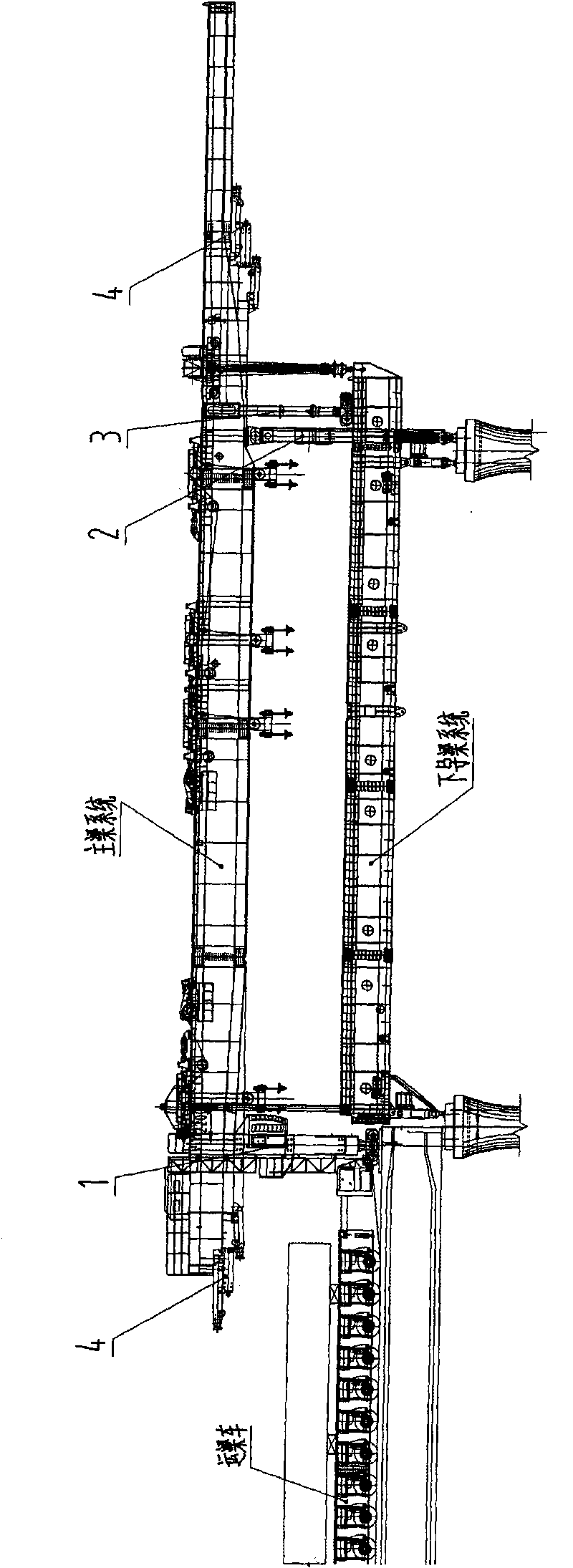
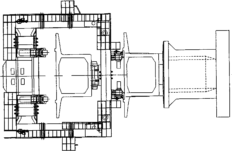
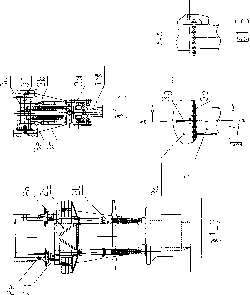
[0025] like figure 1 Shown, the bionic outrigger system of robot cat type railway bridge erecting machine of the present invention comprises the rear support leg 1 (referring to that) that combines with bridge erecting machine main beam system Picture 1-1 ), front outrigger 2 (see Figure 1-2 ), auxiliary outrigger 3 (see Figure 1-3 , Figure 1-4 ), front and rear hydraulic supports 4 (see Figure 8 ).

[0026] like Figure 5 , Figure 5-1 , Figure 5-2 , Figure 5-3 , Image 6 , Figure 6-1 , Figure 6-2 , Figure 7 , Figure 7-1As shown, the rear outrigger 1 is an adjustable rectangular rigid frame structure that can be stretched up and down and narrowed left and right (turn around 90 degrees), including symmetrically arranged left and right columns 5, lower beams 6 and upper beams 7, wherein : Three-section set column type column 5 (one on ea...


PUM


Abstract

The invention relates to a bionic leg system for a machine cat type railway bridge erecting machine, which is characterized by comprising a back leg (1), a front leg (2), an auxiliary leg (3), and front and back hydraulic supports (4), wherein the back leg (1) is combined with a girder system of the bridge erecting machine; the back leg (1) is an adjustable rectangular rigid-frame structural member which can be telescoped up and down and turned for 90 degrees to be retracted and narrowed horizontally; the front leg (2) is a portal structure which can be bent and tilted up; the auxiliary leg (3) comprises an upper beam (3a), two upright columns (3b) and a travelling mechanism (3d); the two upright columns (3b) are in a three sleeved column type and are arranged left and right below the upper beam; the travelling mechanism (3d) is positioned below the upright columns; each of the front and back hydraulic supports (4) comprises a four sleeved-column type long upright column (13), a four sleeved-column type short upright column (14) and a lower sleeper beam (16); and the upper end of a jacking oil cylinder (17) installed on the lower sleeper beam (16) is combined with a girder bottom plate of the bridge erecting machine through two detachable sleeved column type lengthening telescoping middle columns (18).

Description

technical field [0001] The invention relates to bridge construction equipment, in particular to a bionic outrigger system of a robotic cat-type railway bridge erecting machine capable of erecting high-speed railway single-track bridges and passing through single-track tunnels as a whole. Background technique [0002] There are often bridges and tunnels connected or separated by bridges and tunnels on single-track high-speed railway lines. Therefore, when the bridge erecting machine completes the previous bridge and wants to erect the next bridge, it often needs to pass through one or more tunnels in the middle. However, almost without exception, the fuselage section of the bridge erecting machine always exceeds the cross-sectional size of the tunnel. To make the bridge erecting machine pass through the tunnel, the following three methods are adopted: one is to completely disassemble the bridge erecting machine, Bulk transportation passes through the tunnel and then reassembl...

Claims


Application Information

Patent Timeline
Patent Type & Authority Applications(China)
IPC IPC(8): E01D21/00
Inventor 黄耀怡陈浩张志华李淮代宇贾力锋景海州苏春霞陈变玲
Owner ZHENGZHOU NEW DAFANG HEAVY IND & TECH
Learn More