Belt pulley rotating device

A technology of rotating devices and pulleys, which is applied in the direction of transmission devices, belts/chains/gears, mechanical equipment, etc. It can solve problems such as pulley position deviation, damage to other components, wear of pulleys and belts, etc., to improve coaxiality and ensure rotation Accuracy, compact design effect

Inactive Publication Date: 2010-06-30
SUZHOU MINGFU AUTOMATIC SCI & TECH
View PDF0 Cites 8 Cited by
  • Summary
  • Abstract
  • Description
  • Claims
  • Application Information

AI Technical Summary

Problems solved by technology

[0004] Under the existing technology, during the operation of the pulley, the pulley often pushes the rib bearing to move towards the rib bearing, which eventually causes the position of the pulley to deviate, causing the pulley to interfere with the surrounding mechanisms or the belt transported on the pulley to be separated from the pulley. Interference with other parts of the machine, causing wear to pulleys and belts, and damage to other parts

Method used


Image

  • Belt pulley rotating device
  • Belt pulley rotating device

Examples


Embodiment Construction

[0013] The preferred embodiments of the present invention will be described in detail below in conjunction with the accompanying drawings, so that the advantages and features of the present invention can be more easily understood by those skilled in the art, so as to define the protection scope of the present invention more clearly.

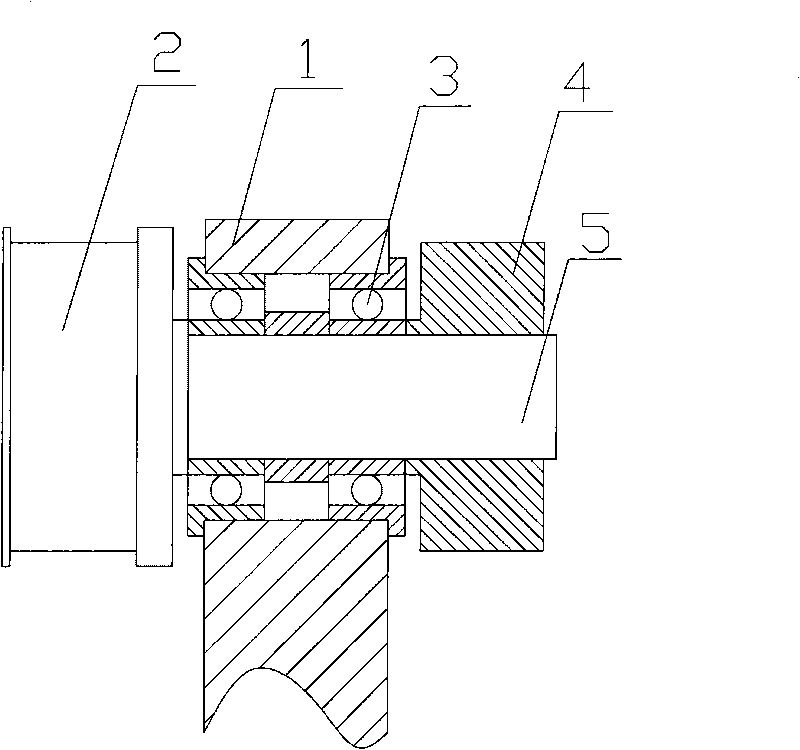
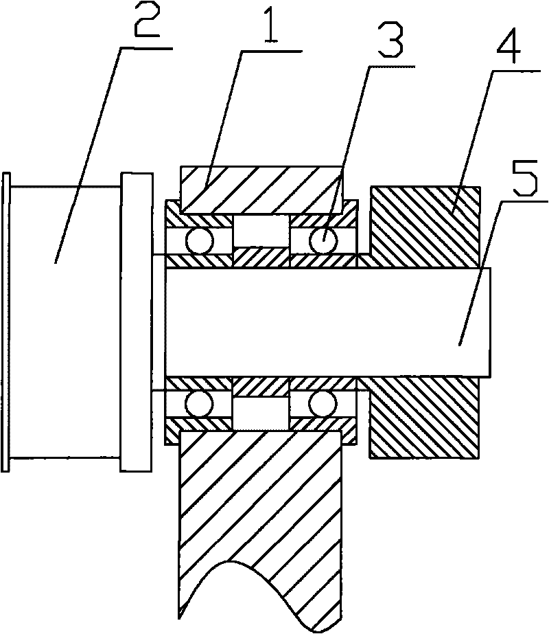
[0014] See attached figure 1 , a pulley rotating device, comprising a rotating shaft 5 connected to the pulley 2, a rib bearing 3 surrounding the rotating shaft 5, a locking ring 4 is also arranged on the rib bearing 3, and the locking ring 4 and the pulley 2 are respectively arranged on On both sides of the rib bearing 3, the outer surface of the rib bearing 3 is also provided with a fixed sleeve 1.

[0015] The fixing sleeve 1 is ring-shaped, and the ring-shaped fixing sleeve 1 matches the shape of the rib bearing 3, which can conveniently fix the rib bearing 3; of course, multiple separate fixing sleeves 1 can also be used to fix the rib beari...


PUM


Abstract

The invention discloses a belt pulley rotating device. The rotating device comprises a rotary shaft (5) connected with a belt pulley (2) and a bearing arranged around the rotary shaft (5), wherein the bearing is provided with a locking ring (4), the locking ring (4) and the belt pulley (2) are arranged on both sides of the bearing respectively, and the outer surface of the bearing is provided with a fixed sleeve (1). The belt pulley turning device has the advantage that the belt pulley turning device can avoid the positional deviation of the belt pulley.

Description

technical field [0001] The invention relates to a pulley rotating device. Background technique [0002] Pulleys are mainly used for long-distance transmission of power, such as the output of small diesel engine power, agricultural vehicles, tractors, automobiles, mining machinery, machining equipment, textile machinery, packaging machinery, lathes, forging machines, some small horsepower motorcycle power Transmission, agricultural machinery power transmission, air compressor, reducer, reducer, generator, cotton gin, etc. [0003] Belt pulleys are often matched with rib bearings. Rib bearings are the most representative rolling bearings. They are widely used and are suitable for high or even extremely high speed operations. They are also very durable and require no frequent maintenance. This type of bearing has small friction coefficient, high limit speed, simple structure, low manufacturing cost, easy to achieve high manufacturing accuracy, and various size ranges and forms...

Claims


Application Information

Patent Timeline
Patent Type & Authority Applications(China)
IPC IPC(8): F16H7/20
Inventor 庄春明
Owner SUZHOU MINGFU AUTOMATIC SCI & TECH
Why Eureka
Try Eureka