Parallel voltage stabilizing circuit

A voltage stabilizing circuit and parallel connection technology, applied in the direction of adjusting electrical variables, control/regulation systems, instruments, etc., can solve problems such as poor anti-interference performance and voltage output stability, rising operating temperature of the adjustment tube Q2, and complex circuit structure. Achieve the effects of low production cost, reduced adjustment frequency, and simple circuit structure

Inactive Publication Date: 2010-06-30
浙江会瑞科技有限公司
View PDF0 Cites 9 Cited by
  • Summary
  • Abstract
  • Description
  • Claims
  • Application Information

AI Technical Summary

Problems solved by technology

But there are also the following three disadvantages: (1), the circuit input voltage VIN and the output voltage VDD are directly connected, and the anti-interference performance and voltage output stability are poor in practical applications; (2), the circuit feedback and the use of the control unit do not have hysteresis comparison The function of the comparator causes the operating point of the adjustment tube Q2 to always be in the amplification area of ​​its output characteristics, resulting in an increase in the operating temperature of the adjustment tube Q2 and a large power consumption
(3) In order for the circuit to work stably, it is necessary to provide a stable external working power supply VCC to the comparator U2, so the circuit structure is complex, there are many application components and the production cost is high

Method used


Image

  • Parallel voltage stabilizing circuit
  • Parallel voltage stabilizing circuit
  • Parallel voltage stabilizing circuit

Examples


Embodiment Construction

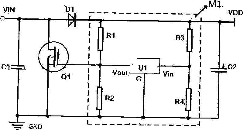
[0017] See image 3 , The parallel voltage stabilizing circuit of this embodiment includes: a voltage detection and control part M1, a regulating transistor Q1 and an isolation diode D1.

[0018] In the voltage detection and control part M1, the output voltage VDD is divided by the resistors R3 and R4 to obtain a feedback voltage, which is input to the input terminal Vin of the voltage comparator U1 with hysteresis characteristics, and the voltage detector U1 compares the input terminal Vin of the input terminal Vin. Voltage and the internal reference voltage (that is, the preset value), to determine whether the current output voltage terminal VDD is consistent with the designed voltage value, if the value deviation exceeds the working range of the voltage hysteresis band, the output terminal of the voltage detector U1 Vout outputs a corresponding adjustment signal. The output terminal Vout of the voltage detector U1 is pulled up to the output voltage VDD through the resistor...


PUM


Abstract

The invention relates to a parallel voltage stabilizing circuit which has large output power, low operation power, simple structure and low cost. The parallel voltage stabilizing circuit comprises a voltage detection and control unit M1, a regulating tube Q1 and an isolated diode D1; wherein the output voltage end VIN is connected with the anode of the isolated diode D1 and the current input end of the regulating tube Q1, the cathode of the isolated diode D1 is connected with the power input end of the voltage detection and control unit M1, and the power output end of the voltage detection and control unit M1 is connected with the output voltage end VDD; the control output end of the voltage detection and control unit M1 is connected with the control end of the regulating tube Q1; the current output end of the regulating tube Q1 is connected with a system ground GND; and the regulating tube Q1 is correspondingly controlled to switch on or off when the voltage detection and control unit M1 detects that the voltage at the output voltage end VDD is higher or lower than a preset value so as to ensure that the output voltage end VDD is stabilized.

Description

technical field [0001] The invention relates to a parallel voltage stabilizing circuit, which is used for converting an input current source into a stable voltage output. Background technique [0002] At present, parallel voltage stabilizing circuits are widely used in the design of voltage stabilizing circuits output by current sources. There are two common parallel voltage regulator circuits: one is such as figure 1 , using a three-terminal voltage regulator tube of model TL431 and a few peripheral devices. In the figure, R5 is a current-limiting resistor, which is connected in series to the adjustment terminal of the input voltage VIN and TL431D1. The output voltage VDD is divided by resistors R6 and R7 to obtain a reference voltage. It is connected to the voltage reference pin Vout of TL431 (D2), and C3 is a filter capacitor connected in series between the output voltage terminal VDD and the system ground GND. Because the device TL431 itself can withstand low power, th...

Claims


Application Information

Patent Timeline
Patent Type & Authority Applications(China)
IPC IPC(8): G05F1/613
Inventor 陈俊梁隆军郑春桥
Owner 浙江会瑞科技有限公司
Why Eureka
Try Eureka