Method for demarcating camera and device thereof

A camera calibration and camera technology, applied in the field of image processing and computer vision, can solve problems such as many restrictions, complex processes, and inability to use calibration reference objects, achieving the effect of fast solution process and stable solution results

Inactive Publication Date: 2012-08-08
HUAWEI TECH CO LTD
View PDF0 Cites 0 Cited by
  • Summary
  • Abstract
  • Description
  • Claims
  • Application Information

AI Technical Summary

Problems solved by technology

[0005] It is necessary to obtain high-precision known scene structure information through reference objects such as calibration blocks or calibration templates, and the process is complicated; and in many practical applications, calibration reference objects cannot be used, and there are many restrictions

Method used


Image

  • Method for demarcating camera and device thereof
  • Method for demarcating camera and device thereof
  • Method for demarcating camera and device thereof

Examples


Embodiment 1

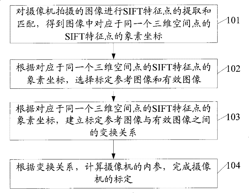
[0044] See figure 1 The embodiment of the present invention provides a method for camera calibration, including:

[0045] 101: Extract and match the scale-invariant feature SIFT feature points of the image taken by the camera, and obtain the pixel coordinates of the SIFT feature points corresponding to the same three-dimensional space point in the image. The image is the same image obtained by rotating the camera around the optical center. At least two images of the scene;

[0046] Among them, the specific implementation 101 includes: extracting the SIFT feature points of the image; performing SIFT feature point matching between the images, where the Euclidean distance of the feature vector of the feature point is used as the basis for judging whether the SIFT feature points in the image match, The nearest neighbor ratio method is used as the judgment rule for matching SIFT feature points in the image, and the sequential loop matching method is used for matching; according to the o...

Embodiment 2

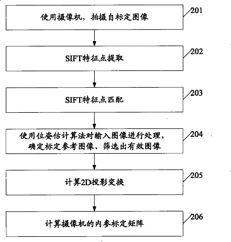
[0055] See figure 2 , The second embodiment of the present invention provides a camera calibration method, including:

[0056] 201: Use a camera to shoot calibration images;

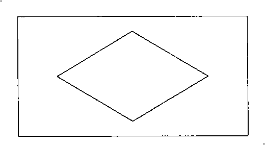
[0057] Among them, the camera is fixed at a position in the 3D world space, and the image sequence of the same scene is taken by rotating around the optical center to different directions, and at least two images of the same scene are taken. In the process of shooting an image sequence, the internal parameter K of the camera is kept unchanged, that is, the focal length of the camera remains unchanged. Suppose that the image sequence taken to the end includes images I0, I1...IN-1, including N images (N≥3). Such as Figure 3a to Figure 3e Shows five images of different angles for calibration in a scene; Figure 4a to Figure 4c Shows another scene with three different angles for calibration.

[0058] 202: SIFT feature point extraction;

[0059] The feature points are extracted for each calibration image. The ex...

Embodiment 3

[0181] See Figure 5 , An embodiment of the present invention provides a camera calibration device, including:

[0182] The feature point processing module 501 is used to extract and match the scale-invariant feature SIFT feature points of the image taken by the camera to obtain the pixel coordinates of the SIFT feature points corresponding to the same three-dimensional space point in the image. The image is the camera surrounding light At least two images of the same scene captured by heart rotation;

[0183] The selection module 502 is configured to select a calibration reference image and a valid image according to the pixel coordinates of the SIFT feature points corresponding to the same three-dimensional space point;

[0184] The establishment module 503 is used to establish the transformation relationship between the reference image and the effective image according to the pixel coordinates of the SIFT feature points corresponding to the same three-dimensional space point;

[01...


PUM


Abstract

The invention discloses a method for demarcating a camera and a device thereof, belonging to the image processing and computer vision fields. The method comprises the following steps of extracting and matching scale-invariant feature transformation (SIFT) characteristic points for an image shot by the camera, and obtaining pixel coordinates corresponding to the SIFT characteristic points in a same 3D space point; choosing a demarcated reference image and an effective image according to the pixel coordinates corresponding to the SIFT characteristic points in the same 3D space point; establishing a transformation relation between the demarcated reference image and the effective image according to the pixel coordinates corresponding to the SIFT characteristic points in the same 3D space point; calculating an internal parameter of the camera according to the transformation relation, and completing demarcating the camera. The device comprises a characteristic point processing module, a selecting module, an establishing module and a calculating module. The invention can achieve the online and real-time demarcation for the internal parameter of the camera without depending on a demarcated reference object and can solve fast, and the result is stable and accurate.

Description

Technical field [0001] The invention relates to the fields of image processing and computer vision, and in particular to a method and device for camera calibration. Background technique [0002] The acquisition process of camera geometric model parameters is called camera calibration. It is an indispensable step in the field of image processing and computer vision to extract 3D spatial information from 2D images. It is widely used in 3D reconstruction, navigation, and visual monitoring. The camera is calibrated under a certain camera model, after processing the image, a series of mathematical transformations and calculation methods are used to obtain the parameters of the camera model. [0003] In the prior art, the traditional method of using the calibration reference material has been widely used, and the two-step method of Tsai is typical. These traditional methods always need to use calibration reference objects during the shooting and calibration process, which brings great i...

Claims


Application Information

Patent Timeline
Patent Type & Authority Patents(China)
IPC IPC(8): G06T7/00G06V10/24
CPCG06K9/32G06V10/24
Inventor 马利庄李灿林刘源
Owner HUAWEI TECH CO LTD
Why Eureka
Try Eureka