Rectangular microstrip patch antenna

A microstrip patch antenna and rectangular technology, applied in the direction of antennas, electrical components, etc., can solve the problems of antenna performance degradation, increase in antenna size, volume or processing complexity, and can not meet the requirements of wireless communication technology, so as to achieve low processing cost, Suppression of backward radiation and easy processing

Active Publication Date: 2010-06-30
SOUTHEAST UNIV
View PDF3 Cites 5 Cited by
  • Summary
  • Abstract
  • Description
  • Claims
  • Application Information

AI Technical Summary

Problems solved by technology

[0010] The problem to be solved by the present invention is: the existing method of widening the bandwidth of a rectangular microstrip patch antenna cannot meet the requirements of wireless communication technology at the cost of increasing the size, volume or processing complexity of the antenna, or even reducing other performances of the antenna

Method used


Image

  • Rectangular microstrip patch antenna
  • Rectangular microstrip patch antenna
  • Rectangular microstrip patch antenna

Examples


Embodiment Construction

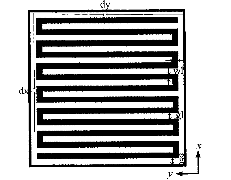
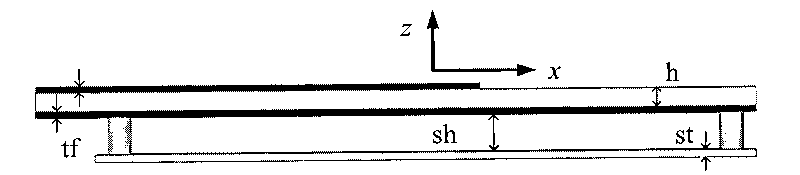
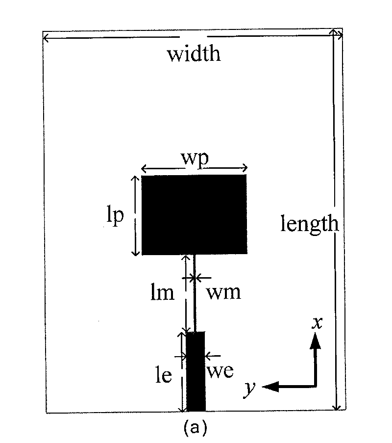
[0024] The present invention includes an upper patch layer, a lower metal floor and a dielectric substrate between the two. Specific patterns are etched on the metal floor, and the entire etching area is located directly below the radiation patch of the upper patch layer. Corresponding to the area, the etching pattern is formed by periodic arrangement of basic planar units in two orthogonal directions in the metal floor, and the basic unit is an embedded curved line structure.

[0025] The periodically arranged embedded curved line structure etched on the metal floor is etched on the copper layer of the copper-clad dielectric substrate by ordinary PCB technology. The embedded curved line structure is an inlaid metal curved line in the rectangular etched area, such as figure 1 , the etching pattern is periodically arranged in two orthogonal directions x and y in the metal floor. The black area in the figure is copper, and the white area represents that the copper in the correspo...


PUM


Abstract

The invention discloses a rectangular microstrip patch antenna, which comprises an upper patch layer, a lower metal floor, and a medium substrate between the upper patch layer and the lower metal floor; and is characterized in that: specific patterns are etched on the metal floor; a whole etching area is positioned under a radiation patch of the upper patch layer and has an area corresponding to that of the radiation patch; the etched patterns are formed by periodically arraying basic planar elements in two orthogonal directions in the metal floor; and the basic planar elements have an embedded bending curve structure. In the antenna, the working frequency band of the antenna is effectively expanded; and a metal baffle is added below the metal floor for restraining the backward radiation of the antenna. The antenna has the advantages of capability of meeting the requirement of the bandwidth of the antenna in the field of wireless communication, no influence on other performance of theantenna, simple manufacturing process, convenient integration with other parts of the system, and relatively low processing expense.

Description

technical field [0001] The invention belongs to the technical field of planar microstrip antennas, can be used in the field of wireless communication, and is a rectangular microstrip patch antenna. Background technique [0002] The development of today's broadband wireless communication technology requires the antenna to have a sufficiently wide operating bandwidth, and it is also hoped that the antenna should be as small and light as possible under the premise of meeting various performance indicators. The traditional microstrip patch antenna uses a dielectric material as the substrate. The bandwidth of the antenna and the size of the radiation patch are a pair of contradictions: the quality factor of the antenna resonance can be reduced by reducing the dielectric constant of the dielectric substrate while maintaining the operating frequency of the antenna. Therefore, the bandwidth of the antenna is increased to a certain extent, but reducing the dielectric constant of the ...

Claims


Application Information

Patent Timeline
Patent Type & Authority Applications(China)
IPC IPC(8): H01Q13/08
Inventor 崔铁军杨歆汩周小阳程强马慧峰
Owner SOUTHEAST UNIV
Why Eureka
Try Eureka