Encircling type vibration generating device

A vibrating power generation, surround-type technology, applied in the direction of electromechanical devices, electrical components, etc., can solve the problem of low utilization rate of magnetic circuit, and achieve the effect of improving power generation efficiency, utilization rate and coil utilization rate

Active Publication Date: 2010-06-30
日照瑞达建设集团有限公司
View PDF4 Cites 8 Cited by
  • Summary
  • Abstract
  • Description
  • Claims
  • Application Information

AI Technical Summary

Problems solved by technology

[0004] The present invention solves the problems of low magnetic circuit utilization rate and improved coil utilization rate of the existing vibration power generation device, and provides a surround-type vibration power generation device with high magnetic circuit utilization rate

Method used


Image

  • Encircling type vibration generating device
  • Encircling type vibration generating device
  • Encircling type vibration generating device

Examples


Embodiment 1

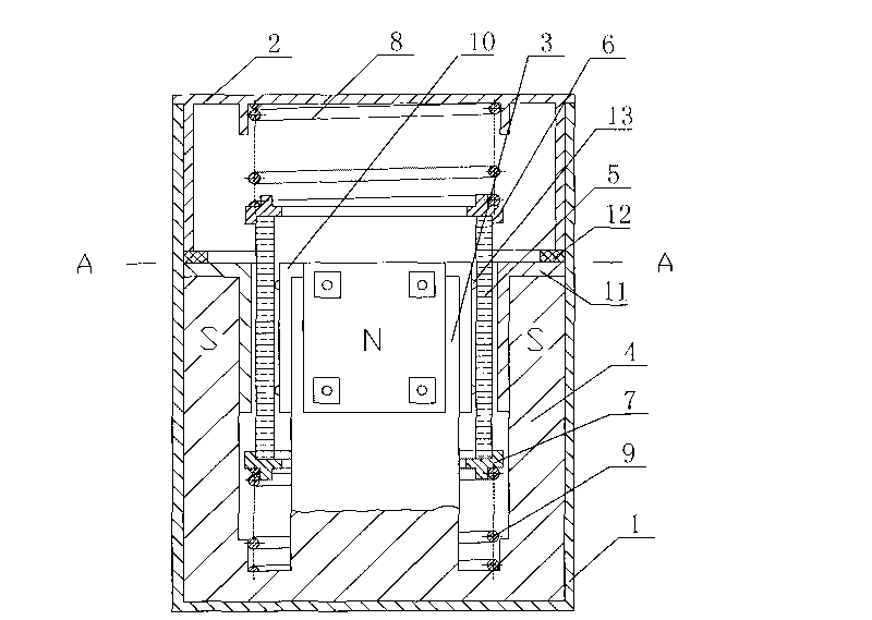
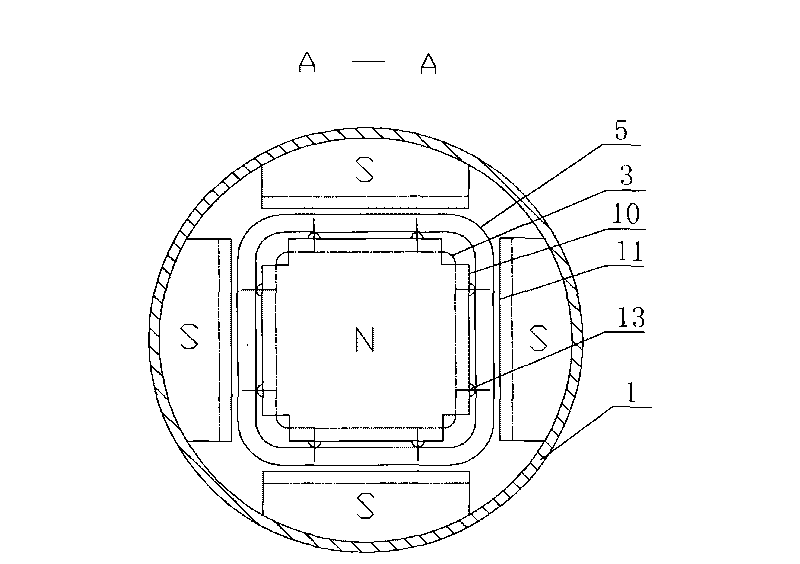
[0022] refer to figure 1 , figure 2 , Surrounding vibration power generation device, comprising a casing 1, the casing 1 is provided with a cover 2, the casing 1 is provided with a flower-shaped bonded permanent magnet, and the middle of the bonded permanent magnet is a square N pole 3, The N pole 3 is surrounded by four S poles 4, and the S poles 4 are symmetrically distributed in a cross, and their bottoms are connected together and connected to the N pole 3; between the N pole 3 and the S pole 4, a Coil 5, the upper and lower ends of the coil 5 are provided with square deck frames 6, 7, the upper deck frame 6 and the lower deck frame 7 are respectively connected with springs 8, 9, the lower deck frame 7 Set on the N pole 3, the lower end of the lower spring 9 is connected to the bottom of the S pole 4, and the upper end of the upper spring 8 is fixed on the cover 2.

[0023] The housing 1 is a cylindrical structure.

[0024] The bonded permanent magnet is formed by mixi...

Embodiment 2

[0033] The difference between this embodiment and the first embodiment is that the ball 13 is made of duralumin. The duralumin material will not have a suction effect, and the friction force will be low when rolling, but it will not have the benefit of reducing the local air gap. Other structures and functions are the same as those in Embodiment 1.


PUM


Abstract

The invention relates to an encircling type vibration generating device which comprises a shell, wherein a cover is arranged on the shell; a flower-shaped bonding permanent magnet is arranged in the shell; a square N pole is arranged in the middle of the permanent magnet, and four S poles are arranged around the permanent magnet; a first ferromagnetic material cushion layer and a second ferromagnetic material cushion layer are covered on the S poles and the N pole; the first ferromagnetic material cushion layer is pressed on the S poles through a rubber washer at the lower end of the cover; a coil is installed between the N pole and each of the S poles; square cassette frames which are connected with springs are arranged at the upper end and the lower end of the coil; the lower end of the lower spring is connected with the bottom of each of the S poles, and the upper end of the upper spring is fixed on the cover; a closed main magnetic circuit which starts from the N pole, passes through the second ferromagnetic material cushion layer, air gaps, the first ferromagnetic material cushion layer and the S poles, and then backs to the N pole is formed in the device; and the coil cuts the main magnetic circuit up and down along with the external vibration to generate electricity. The invention has the beneficial effects of improving the utilization ratio of the magnetic circuit and the coil and the generating efficiency, and has compact structure and wide application range.

Description

technical field [0001] The invention relates to a vibration power generating device. Background technique [0002] The problem of powering wireless sensor networks or distributed small systems is a difficult point. Vibration is a form of energy in nature. For example, the waves of the sea, the swing of branches in the wind, bumpy vehicles, etc. Vibration power generation is to convert the energy generated by various vibrations into electrical energy. It is a potential new power generation device that is pollution-free and does not consume natural resources. It is suitable for wireless sensor networks or distributed small system nodes. [0003] One way to achieve vibration power generation is through the phenomenon of electromagnetic induction. Conventional electromagnetic induction vibration power generation devices have different internal structures. The vibration generator with the application number 200410067821.3, the three-dimensional vibration generator with the ap...

Claims


Application Information

Patent Timeline
Patent Type & Authority Applications(China)
IPC IPC(8): H02K35/04
Inventor 张端张松何熊熊
Owner 日照瑞达建设集团有限公司
Why Eureka
Try Eureka