Compound co-extrusion conical screw extruder

A conical screw and extruder technology, which is applied in the field of compound co-extruded conical screw extruders, can solve the problems of affecting the appearance and quality of products, large equipment footprint, and large equipment investment, so as to avoid weld lines” traces, improved conveying capacity and output, and easy maintenance

A conical screw and extruder technology, which is applied in the field of compound co-extruded conical screw extruders, can solve the problems of affecting the appearance and quality of products, large equipment footprint, and large equipment investment, so as to avoid weld lines” traces, improved conveying capacity and output, and easy maintenance

CN101767435AInactive Publication Date: 2010-07-07BEIJING UNIV OF CHEM TECH

Image

  • Compound co-extrusion conical screw extruder
  • Compound co-extrusion conical screw extruder
  • Compound co-extrusion conical screw extruder

Examples


Embodiment Construction

[0014] specific implementation plan

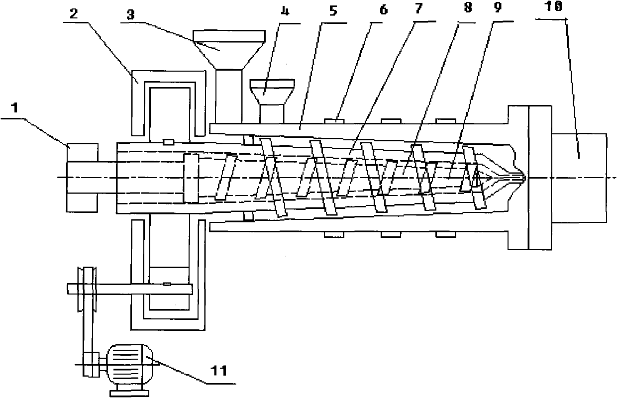
[0015] The composite co-extrusion conical screw extruder of the present invention mainly comprises: motor 11, reduction box 2, machine barrel 5, outer screw 7, inner screw 8, stator 1, first feeding port 4, second feeding port 3, machine barrel Heating ring 6, internal screw heating device 9, die 10.

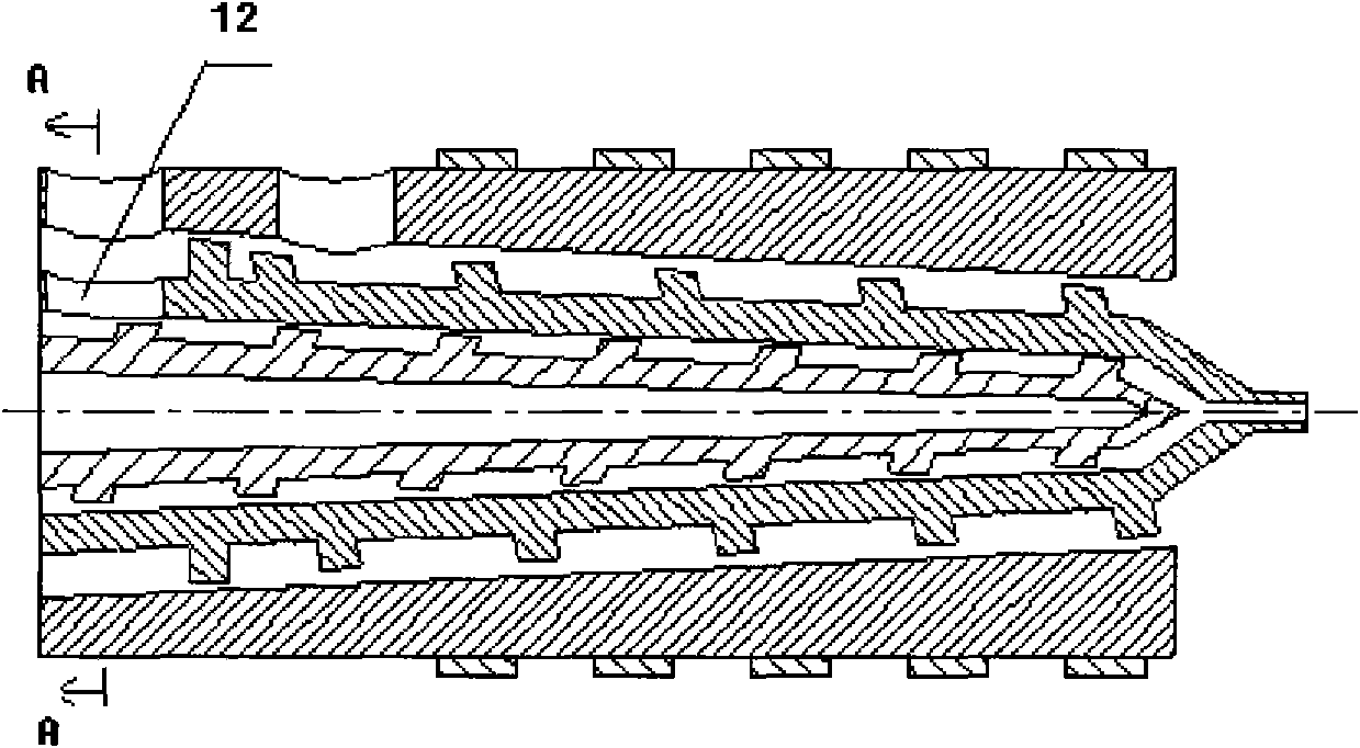
[0016] How it works (see figure 1 ): When the motor drives the outer screw to rotate, it produces an opposite rotational motion with the inner screw (fixed or driven by the motor alone). A material is fed from the hopper 4, and enters the external screw for extrusion, transportation, plasticization, and melting. Another material is added from the hopper 3, and enters the closed material storage room formed by the annular groove at the front end of the outer screw and the inner surface of the barrel, distributed along the circumferential direction of the outer screw annular groove, and enters from the feeding hole 12 of the annular storage ...


PUM


Abstract

The invention relates to a compound co-extrusion conical screw extruder which mainly consists of a charging device, a cylinder, screws, an extruder head, a motor and a driving device. The embedded inner screw and outer screw are arranged in the cylinder. The screwing directions of the inner screw and the outer screw are opposite, and the inner screw and the outer screw do reverse opposite rotation. The two screws can adopt three combination methods that: the inner screw is a conical screw, and the outer screw is a parallel screw; the inner screw is a parallel screw, and the outer screw is a conical screw; and the inner screw and the outer screw are all the conical screws. The embedded screws are connected with the same extruder head. The invention realizes single-machine double-layer co-extrusion, thereby decreasing the quality of the co-extruder hosts, saving the investment and land occupation space of equipment, simultaneously exerting the advantages of the conical screws and enhancing the extruding efficiency and the product processing quality.

Description

technical field [0001] The composite co-extrusion conical screw extruder of the present invention can be used for composite co-extrusion of plastic products such as composite plates, films, pipes, sheets, optical fiber cables, and the like. Background technique [0002] Composite co-extrusion is a processing method in which two or more polymers with different properties are co-extruded to form a multi-layer single product. Such as multi-layer sheets, films, plates, pipes, cables and multi-layer hollow containers. At present, most of the equipment used for composite co-extrusion is composed of two or more than two screw extruders, and different materials are extruded into the co-extrusion die for compounding. The equipment investment is large and complex, and the equipment occupies an area of Larger, especially the more layers of composite products, the more prominent this problem is, in addition, the molten materials from different extruder barrels need to be redistributed ...

Claims


Application Information

Patent Timeline
07 Jul 2010
Publication
CN101767435A
IPC
B29C47/08; B29C47/12; B29C47/60; B29C47/78; B29C48/30; B29C48/515
CPC
B29C47/48; B29C47/46; B29C48/455; B29C48/445; B29C48/832; B29C48/845; B29C48/515
Inventors
王克俭