Method for reconstructing three-dimensional reciprocal space of material with complex structure
A reciprocal space and complex structure technology, applied in the field of characterization of complex structures, can solve the problems of limited recording size and susceptibility to electron radiation damage, and achieve the effect of reducing radiation damage and high efficiency
- Summary
- Abstract
- Description
- Claims
- Application Information
AI Technical Summary
Problems solved by technology
Method used
Image
Examples
Embodiment 1
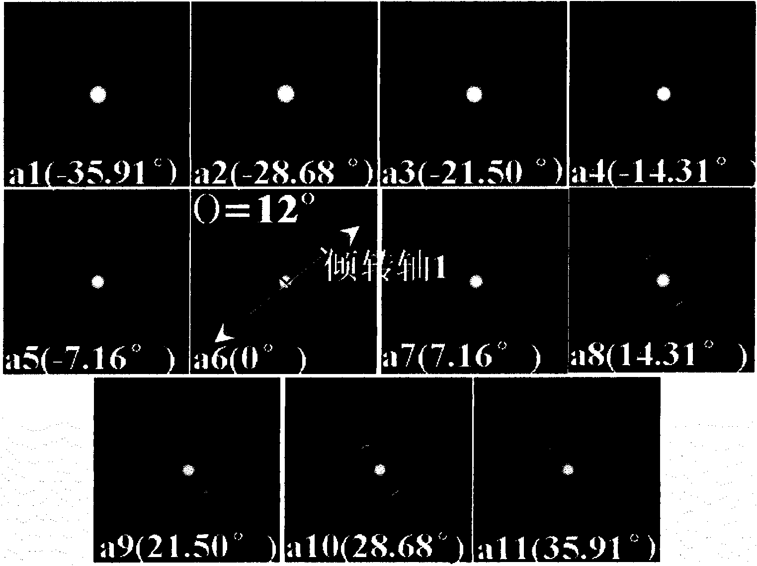
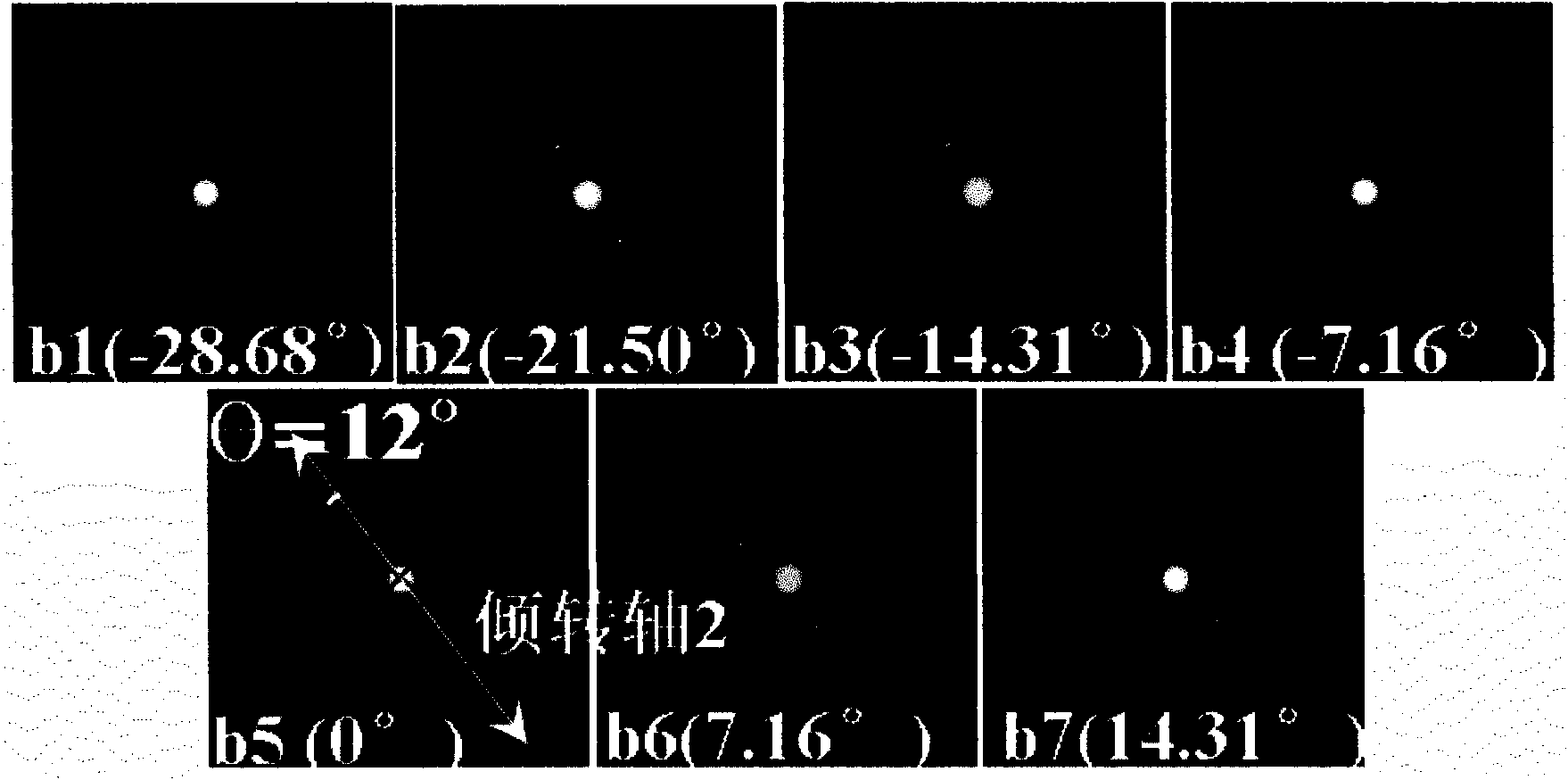
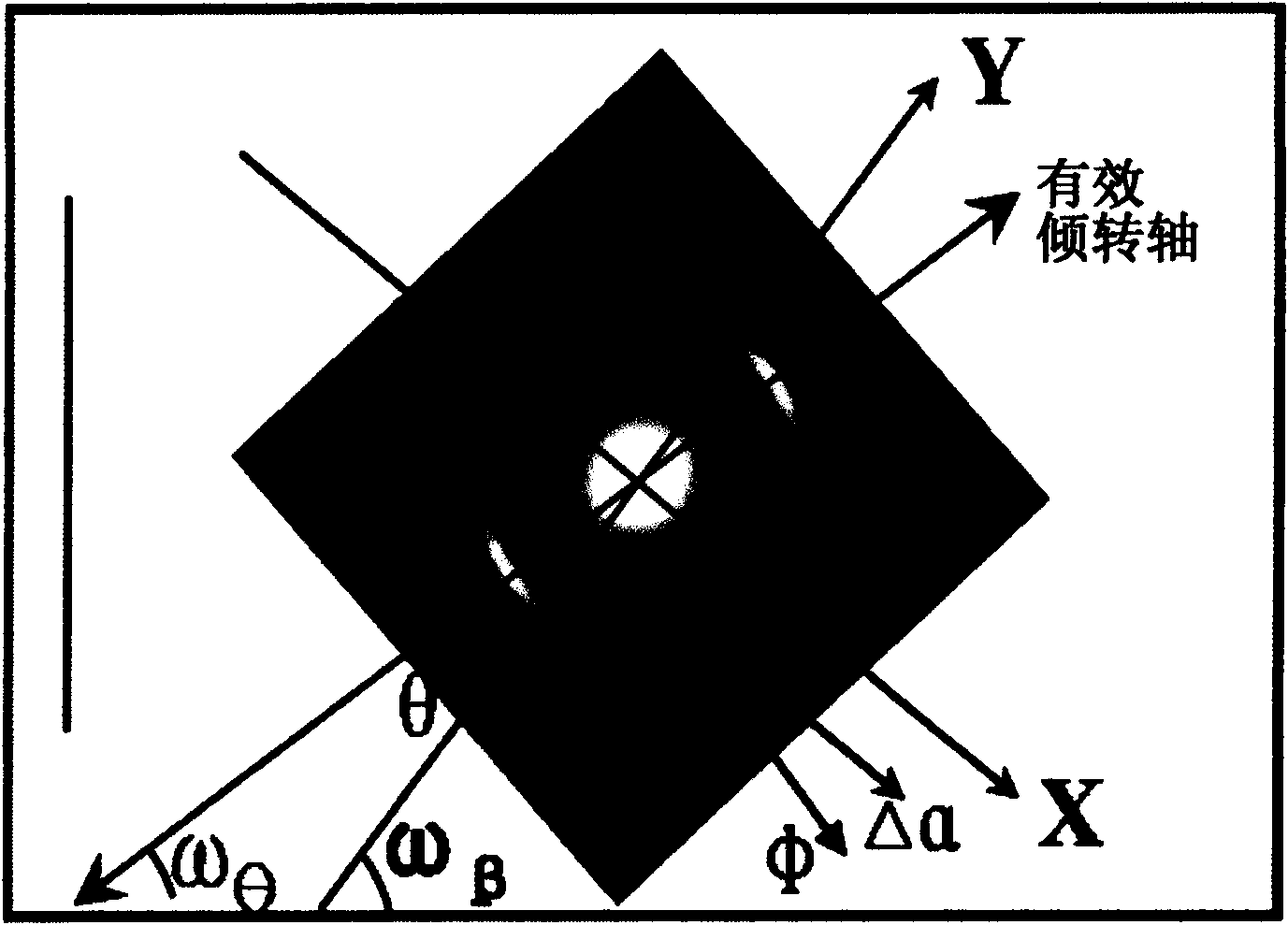
[0046] like figure 1 As shown, XYZO is the spatial coordinate of the sample in the transmission electron microscope. Before tilting, the initial crystal plane normal of the sample is set to be parallel to the OZ axis, and the effective tilting axis is selected as OB'. After the main tilting axis of the sample stage is rotated α (the initial crystal plane normal is parallel to OA), the secondary tilting axis of the sample stage is rotated β (initial The crystal plane normal is parallel to OA') and then the first tilt is completed (the total rotation angle is Ф). At this time, if OA=OA'=1, the geometric relationship between the main inclination angle α of the sample stage, the secondary inclination angle β of the sample stage and the effective inclination angle θ can be established: tanθ=sinβ / tanα. The above formula can be rewritten as Δβ i =arcsin(tanΔα i ×tanθ). Selecting the tilt step size Δα for the tilted electron diffraction reconstruction experiment i Finally, calcul...
Embodiment 2
[0055] Embodiment 2: The inverted spatial drum-shaped distribution characteristics of PAN-based carbon fibers determined by the present invention
[0056] Before formally applying this method to the PAN-based carbon fiber sample, first calculate the projection angle of the tilting axis of the sample stage of the transmission electron microscope used on the film through the tilting electron diffraction experiment of the single crystal sample as described in step 1 in Example 1 Under the selected camera constant as figure 2 49° shown.
[0057]In the low-magnification imaging mode of the transmission electron microscope, look for the thin area of the carbon fiber; combine the selected area electron diffraction to determine the selected area of the carbon fiber to be tilted (it is better to have obvious features in the shape, so that it can be identified after tilting) such as Figure 7 shown. According to the method described in step 2 to 5 in embodiment 1, keep as Figur...
Embodiment 3
[0059] Example 3: Inverted spatial umbrella-shaped distribution characteristics of graphite crystallite orientation of pyrolytic carbon determined by the present invention
[0060] Before formally applying this method to the pyrolytic carbon sample in the carbon-carbon composite material, as described in step 1 in Example 1, the tilting axis of the sample stage of the transmission electron microscope used was first calculated through the tilting electron diffraction experiment of the single crystal sample at The projection angle on the film is as follows under the selected camera constant figure 2 49° shown.
[0061] In the low-magnification imaging mode of the transmission electron microscope, look for the thin area of the pyrolytic carbon; combine the selected area electron diffraction to determine the selected area of the pyrolytic carbon to be tilted, such as Figure 7 shown. According to the method described in step 2 to 5 in embodiment 1, keep as Figure 11 The e...
PUM
 Abstract
Description
Claims
Application Information
 - R&D
- Intellectual Property
- Life Sciences
- Materials
- Tech Scout
- Unparalleled Data Quality
- Higher Quality Content
- 60% Fewer Hallucinations
Browse by: Latest US Patents, China's latest patents, Technical Efficacy Thesaurus, Application Domain, Technology Topic, Popular Technical Reports.
© 2025 PatSnap. All rights reserved.Legal|Privacy policy|Modern Slavery Act Transparency Statement|Sitemap|About US| Contact US: help@patsnap.com


