Device for testing radial magnetic field sensitivity of fiber optic gyro

A technology of radial magnetic field and fiber optic gyroscope, applied in the direction of measuring devices, instruments, etc., to achieve the effect of reducing influence, uniform distribution of magnetic field, and improving measurement speed

Inactive Publication Date: 2010-07-07
ZHEJIANG UNIV
View PDF0 Cites 7 Cited by
  • Summary
  • Abstract
  • Description
  • Claims
  • Application Information

AI Technical Summary

Problems solved by technology

There is no test device that meets the above requirements in the current prior art, so there is an urgent need for a device that can accurately cont

Method used


Image

  • Device for testing radial magnetic field sensitivity of fiber optic gyro
  • Device for testing radial magnetic field sensitivity of fiber optic gyro
  • Device for testing radial magnetic field sensitivity of fiber optic gyro

Examples


Example Embodiment

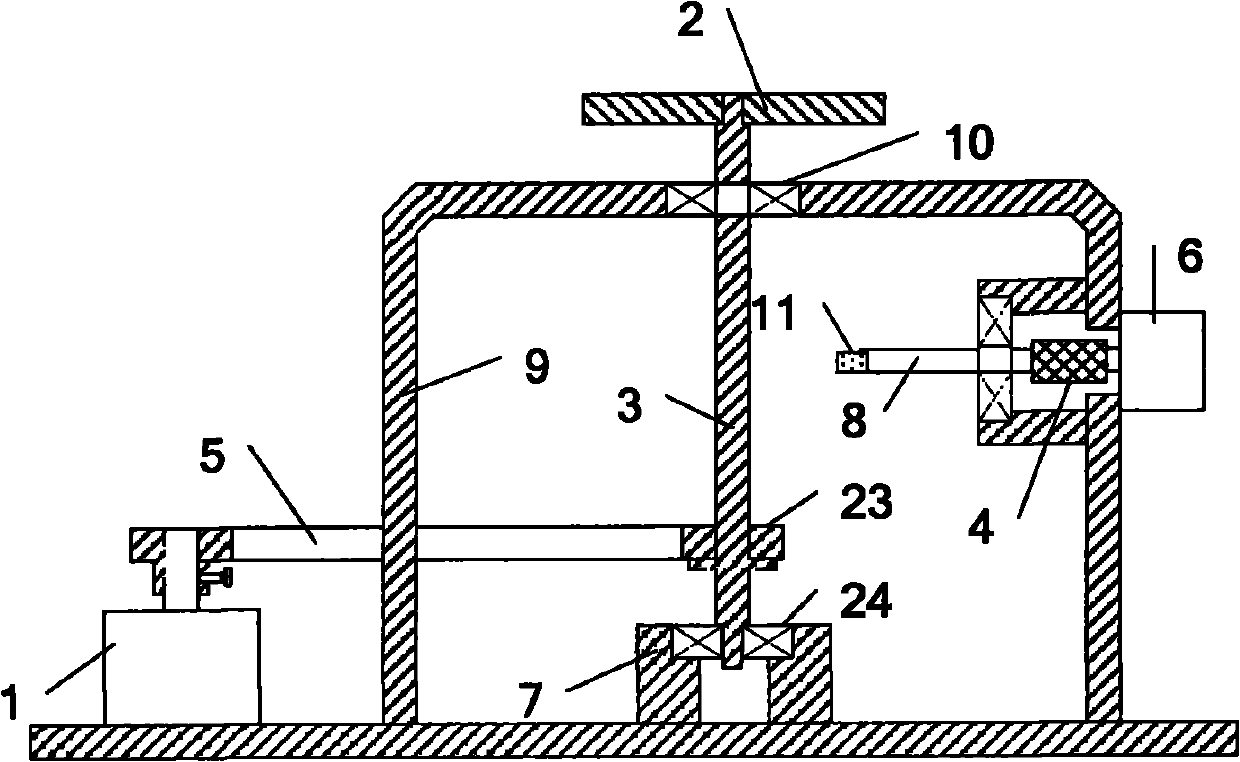
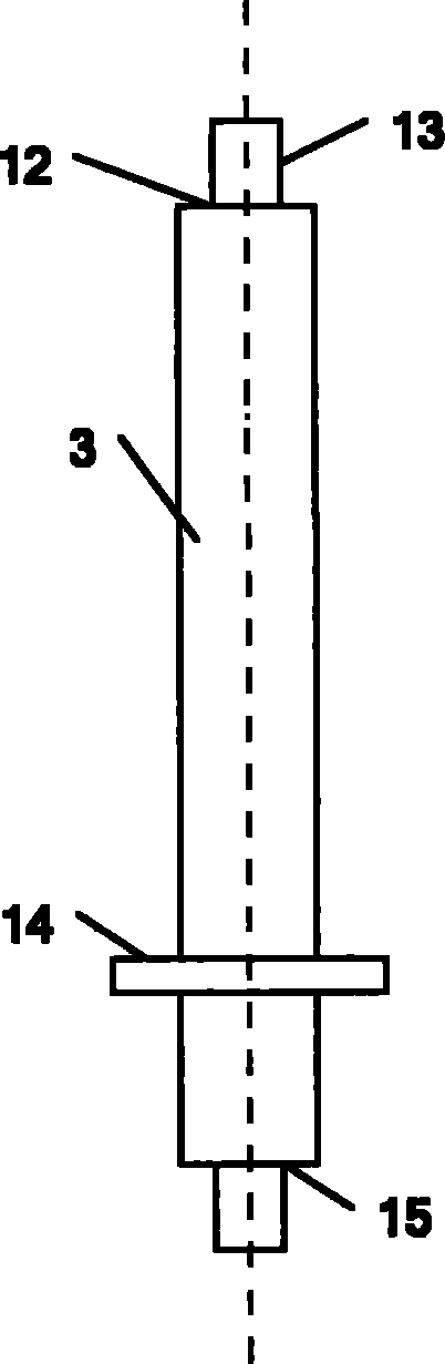
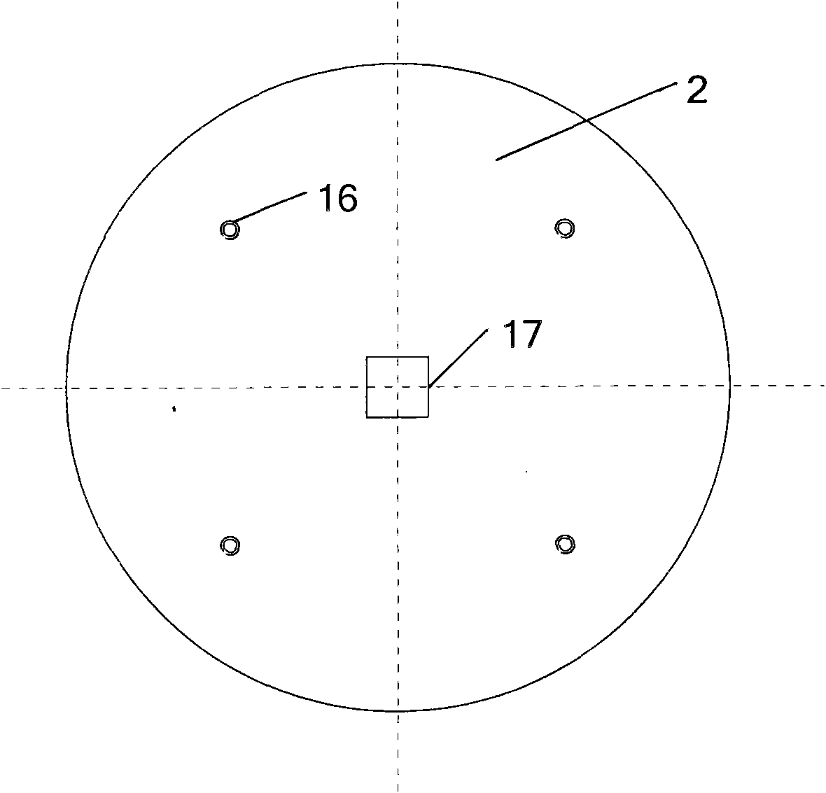
[0014] Such as figure 1 As shown, the testing device of the present invention has a bracket 9 on which a bearing seat 7 is fixedly installed. Such as figure 2 with image 3 As shown, the work surface 2 of the turntable is provided with threaded holes 16 for fixing the fiber optic gyroscope. The rotating shaft 3 of the turntable is a stepped shaft, and a square shaft head 13 is provided at the upper end of the rotating shaft 3, which can closely fit with the square hole 17 in the center of the work surface 2 of the turntable. The shoulder 12 of the rotating shaft 3 is used to limit the work surface 2 of the turntable. One end of the rotating shaft 3 of the turntable close to the work surface 2 of the turntable is mounted together with the support 9 through the rolling bearing 10; the other end of the rotating shaft 3 is connected to the bearing seat through the rolling bearing 24 7 are installed together, the shoulder 15 at this end of the rotating shaft 3 can axially limit the...


PUM


Abstract

The invention discloses a device for testing radial magnetic field sensitivity of a fiber optic gyro, mainly comprising a rotary table, a support, a bearing pedestal fixedly connected with the support, a first electrical machine and a second electrical machine; wherein a revolving shaft of the rotary table is respectively arranged with the support and the bearing pedestal by a rolling bearing, a driving band is arranged at the position where the revolving shaft, the support and the bearing pedestal are arranged, the revolving shaft is connected with a driving shaft of the first electrical machine by the driving band, the driving shaft of the second electrical machine is fixedly connected with a second revolving shaft by a shaft coupler, the second revolving shaft is fixedly provided with a Hall sensor. The device of the invention can be employed to fast test radial magnetic field sensitivity of a fiber optic gyro, features low cost, simple structure, easy adjustment, convenient operation and accurate and reliable testing.

Description

technical field [0001] The invention relates to a test device for the radial magnetic field sensitivity of an optical fiber gyroscope. Background technique [0002] Fiber optic gyro is a sensor sensitive to angular rate and angular deviation based on the Sagnac effect. It has the characteristics of fast response, high sensitivity, long life, easy manufacture, easy integration, and strong environmental adaptability. In practical applications, the fiber optic gyro is disturbed by the environment, resulting in signal drift, and the accuracy is greatly affected. The external magnetic field is an important factor affecting the accuracy of the fiber optic gyroscope. Due to the existence of the magneto-optical effect, the polarization state of the light wave in the fiber optic gyroscope changes due to the influence of the external magnetic field, causing non-reciprocal phase drift and phase difference. The size and direction of the magnetic field change, which affects the zero bia...

Claims


Application Information

Patent Timeline
IPC IPC(8): G01C25/00
Inventor 张登伟华琪车双良舒晓武刘承
Owner ZHEJIANG UNIV
Why Eureka
Try Eureka