
Low bend loss optical fiber

A bending loss, optical fiber technology, applied in clad optical fibers, multi-layer core/clad optical fibers, light guides, etc., can solve problems such as poor optical characteristics, and achieve the effect of minimizing stress and leakage mode dispersion

Inactive Publication Date: 2010-07-07
SAMSUNG ELECTRONICS CO LTD
View PDF0 Cites 25 Cited by
  • Summary
  • Abstract
  • Description
  • Claims
  • Application Information

AI Technical Summary

Problems solved by technology

[0010] However, the problem is that conventional optical fibers have relatively poor optical properties in terms of light loss due to bending

Method used


Image

  • Low bend loss optical fiber
  • Low bend loss optical fiber
  • Low bend loss optical fiber

Examples


Embodiment Construction

[0022] Exemplary embodiments of the present invention will be described with reference to the accompanying drawings. Also, in the following description of the present invention, a detailed description of known functions and structures incorporated herein is omitted when it would make the subject matter of the present invention unclear.

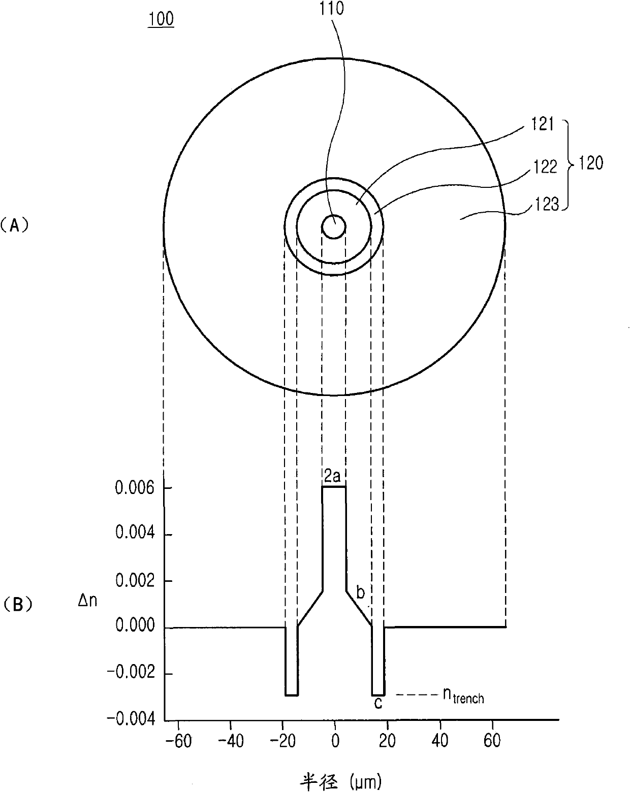
[0023] figure 1 (A) is a cross-sectional view of the optical fiber according to the first embodiment of the present invention, and figure 1 (B) is shown according to figure 1 (A) A graph of the refractive index profile of the fiber cross-section shown. refer to figure 1 , the optical fiber 100 includes a core 110 and a cladding 120 . The core 110 is located at the center of the optical fiber, has a relatively high refractive index, and is used for optical signal transmission through total internal reflection. The cladding 120 is disposed outside the core 110 and has a relatively low refractive index. In other words, the cladding 120 is a...


PUM


Abstract

Disclosed is a low bend loss optical fiber including: a core; an inner layer disposed at outside of the core, which has a refractive index lower than a refractive index of the core, the refractive index of the inner layer gradually decreasing as it becomes farther from the core; and a trench layer disposed at outside of the inner layer, which has a lowest refractive index.

Description

[0001] priority [0002] This application claims the application titled "Low Bend Loss Optical Fiber" and assigned serial number No. 10-2008-0130295 filed with the Korean Intellectual Property Office on December 19, 2008 and the Korean Intellectual Property Priority to an application filed with the Office entitled "Low BendLoss Optical Fiber" and assigned Serial No. 10-2009-0111472, the contents of which are hereby incorporated by reference. technical field [0003] The present invention relates to optical fibers, and more particularly to low bending loss optical fibers. Background technique [0004] At present, with the establishment of FTTH (fiber-to-the-home) user transmission service network with a rate of 100Mbps or higher and the rise of related service industries, the demand for enhanced bending-resistant optical fibers for broadband transmission is growing rapidly. [0005] The common passive optical network (PON) used to construct FTTH includes an optical line term...

Claims


Application Information

Patent Timeline
Patent Type & Authority Applications(China)
IPC IPC(8): G02B6/036
CPCG02B6/0365G02B6/03627G02B6/0283G02B6/0285
Inventor 尹暎植李永燮金镇汉韩元泽朱晟敏吴大焕
Owner SAMSUNG ELECTRONICS CO LTD
Learn More