
Preparation method for cast steel roller

A cast steel roll and roll technology, applied in the field of casting, can solve the problems of reducing the mechanical properties and service performance of the roll, the roll is prone to pores, and the production cost of the roll is increased, so as to achieve high production rate of molten steel process and good hardness uniformity of the roll surface. , the effect of reducing production energy consumption

Inactive Publication Date: 2010-07-14
BEIJING UNIV OF TECH
View PDF3 Cites 0 Cited by
  • Summary
  • Abstract
  • Description
  • Claims
  • Application Information

AI Technical Summary

Problems solved by technology

[0003] However, in the production of cast steel rolls, there are still the following problems: one is that the cast steel rolls have a large shrinkage, and the compactness of the roll structure is poor, which leads to a decrease in the strength of the rolls, and roll breakage accidents are prone to occur during use, which affects the normal production of the rolling mill; In the process of pouring large cast steel rolls, if the molten steel is directly poured from the sprue cup to the mold cavity, the molten steel is easy to wash away the mold coating, resulting in more inclusions in the roll, reducing the mechanical properties and serviceability of the roll; The third is that in the pouring project of molten steel directly from top to bottom, it is easy to mix the gas in the mold into the molten steel, so that pores are easy to appear in the roll, which reduces the mechanical properties and serviceability of the roll, and in severe cases, the cast steel roll is scrapped
However, the no-flow pouring equipment is complicated and expensive, which leads to an increase in the production cost of the roll

Method used


Image

  • Preparation method for cast steel roller

Examples


Embodiment 1

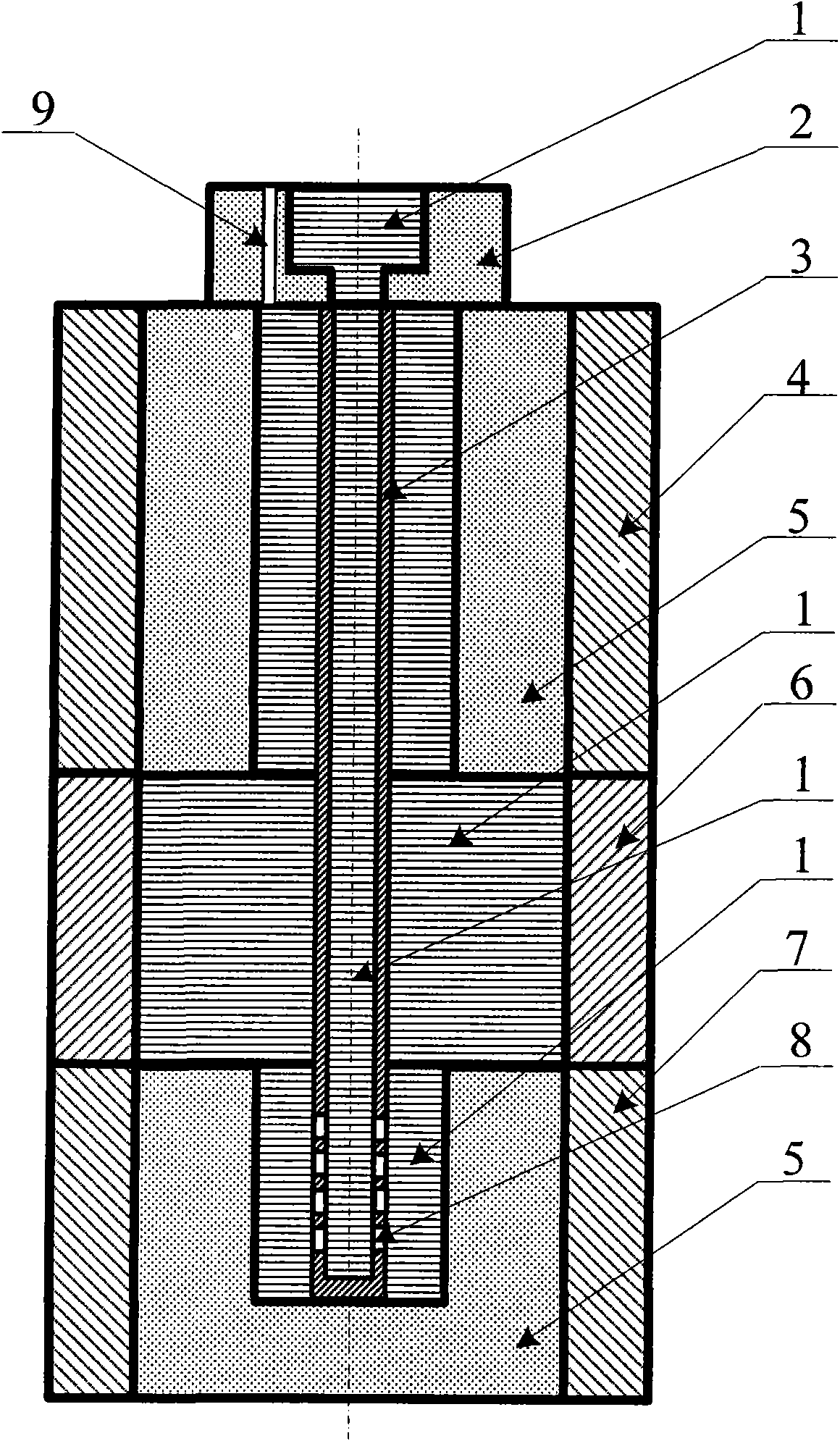
[0019] A 3-ton electric furnace is used to smelt 75CrMo cast steel roll material, and a cast steel roll with a weight of 2.8 tons is cast. When the composition of molten steel meets the requirements, it is released from the furnace. The middle box metal mold (6) is placed on the upper end of the bottom box metal mold (7), the upper box metal mold (4) is placed on the upper end of the middle box metal mold (6), and the sprue cup (2) is placed on the upper box On the top of the sand mold (5) in the metal casting mold (4), an air vent (9) is also arranged on the sprue cup (2), and the air vent (9) communicates with the mold cavity. The casting pipe (3) is installed in the center of the roll mould, the upper end of the casting pipe (3) is directly connected with the sprue cup (2), and the lower end of the casting pipe (3) is directly connected with the bottom box mold (8). The sand mold (5) is connected, the upper end of the casting pipe is open, the lower end is closed, and 15 r...

Embodiment 2

[0021]A 15-ton electric furnace is used to smelt 70Mn2 cast steel roll material, and a cast steel roll with a weight of 12 tons is cast. When the composition of molten steel meets the requirements, it is released from the furnace. The middle box metal mold (6) is placed on the upper end of the bottom box metal mold (7), the upper box metal mold (4) is placed on the upper end of the middle box metal mold (6), and the sprue cup (2) is placed on the upper box On the top of the sand mold (5) in the metal casting mold (4), an air vent (9) is also arranged on the sprue cup (2), and the air vent (9) communicates with the mold cavity. The casting pipe (3) is installed in the center of the roll mould, the upper end of the casting pipe (3) is directly connected with the sprue cup (2), and the lower end of the casting pipe (3) is directly connected with the bottom box mold (8). The sand molds (5) are connected, the upper end of the casting pipe is open, the lower end is closed, and 35 r...

Embodiment 3

[0023] A 10-ton electric furnace is used to melt 75CrNiMo cast steel roll material, and a cast steel roll with a weight of 6 tons is cast. When the composition of molten steel meets the requirements, it is released from the furnace. The middle box metal mold (6) is placed on the upper end of the bottom box metal mold (7), the upper box metal mold (4) is placed on the upper end of the middle box metal mold (6), and the sprue cup (2) is placed on the upper box On the top of the sand mold (5) in the metal casting mold (4), an air vent (9) is also arranged on the sprue cup (2), and the air vent (9) communicates with the mold cavity. The casting pipe (3) is installed in the center of the roll mould, the upper end of the casting pipe (3) is directly connected with the sprue cup (2), and the lower end of the casting pipe (3) is directly connected with the bottom box mold (8). The sand mold (5) is connected, the upper end of the casting pipe is open, the lower end is closed, and 20 r...


PUM

PropertyMeasurementUnit
Diameteraaaaaaaaaa
The inside diameter ofaaaaaaaaaa

Abstract

The invention discloses a preparation method for cast steel roller. A casting pipe is installed at the central part of a casting mould firstly. The upper end of the casting pipe is directly connected with a pouring cup. The lower end of the casting pipe is directly connected with sand mould in a bottom box casting mould. The upper end of the casting pipe is open and the lower end of the casting pipe is closed. Fifteen to forty circular holes with diameter of 6mm-20mm are arranged at the lower end of the casting pipe. Molten steel with required components, which is well smelted, is poured into the roller casting mould. During molten steel casting, the molten steel enters the casting pipe through the pouring cup and then enters the lower end of the casting mould cavity through the circular holes at the lower end of the casting pipe, the molten steel is filled into the casting mould from bottom up till the casting mould is filled with the molten steel, and finally the casting pipe is inlaid at the central part of the roller. The invention has the advantages of compact roller structure, less impurity, high strength, good wear resistance, long service life and good economic benefit after popularization.

Description

technical field [0001] The invention relates to a method for preparing a roll, in particular to a method for preparing a cast steel roll, and belongs to the technical field of casting. technical background [0002] Cast steel rolls can be divided into two categories: steel rolls (0.4-1.4% carbon content) and semi-steel rolls (1.4-2.4% carbon content). The steel roll has low carbon content, so its hardness is low. Its structure is generally composed of ferrite and pearlite. As the carbon content increases, the amount of ferrite decreases and the amount of pearlite increases. In order to increase the hardness, alloy elements such as Cr, Ni, Mo can be added, or special heat treatment can be carried out. Because the steel roll has high tensile strength and toughness, it is suitable for billet rolling mill or blooming mill with high rolling temperature and heavy rolling load. , can also be used as a support roller. If special heat treatment is carried out to obtain high hardnes...

Claims


Application Information

Patent Timeline
IPC IPC(8): B22D11/18
Inventor 符寒光雷永平吴中伟林健
Owner BEIJING UNIV OF TECH
Learn More