Hydraulic transmission loop of diagonal cutter shearing machine

A technology of hydraulic transmission and shearing machine is applied in the field of steel sheet processing, which can solve the problems of increasing equipment cost and equipment volume.

Inactive Publication Date: 2010-07-14
NORTHEASTERN UNIV
View PDF0 Cites 10 Cited by
  • Summary
  • Abstract
  • Description
  • Claims
  • Application Information

AI Technical Summary

Problems solved by technology

[0003] For the existing hydraulic shearing circuit, if it is necessary to ensure rapid shearing while ensuring no-load fast forwarding, it is necessary to select a large-capacity accumulator, which increases the cost and volume of the equipment. The present invention provides a A kind of hydraulic transmission circuit of oblique blade shearing machine. When the circuit is empty, the rapid advance of the shearing cylinder is realized through the hydraulic differential circuit without the need for the accumulator to be put into work; When working, the accumulator is put into work, the rodless side of the shearing cylinder enters the high-pressure oil, and the rod side receives the oil, so as to realize the high force output of the shearing cylinder and ensure the high shearing speed

Method used


Image

  • Hydraulic transmission loop of diagonal cutter shearing machine
  • Hydraulic transmission loop of diagonal cutter shearing machine
  • Hydraulic transmission loop of diagonal cutter shearing machine

Examples


Embodiment 1

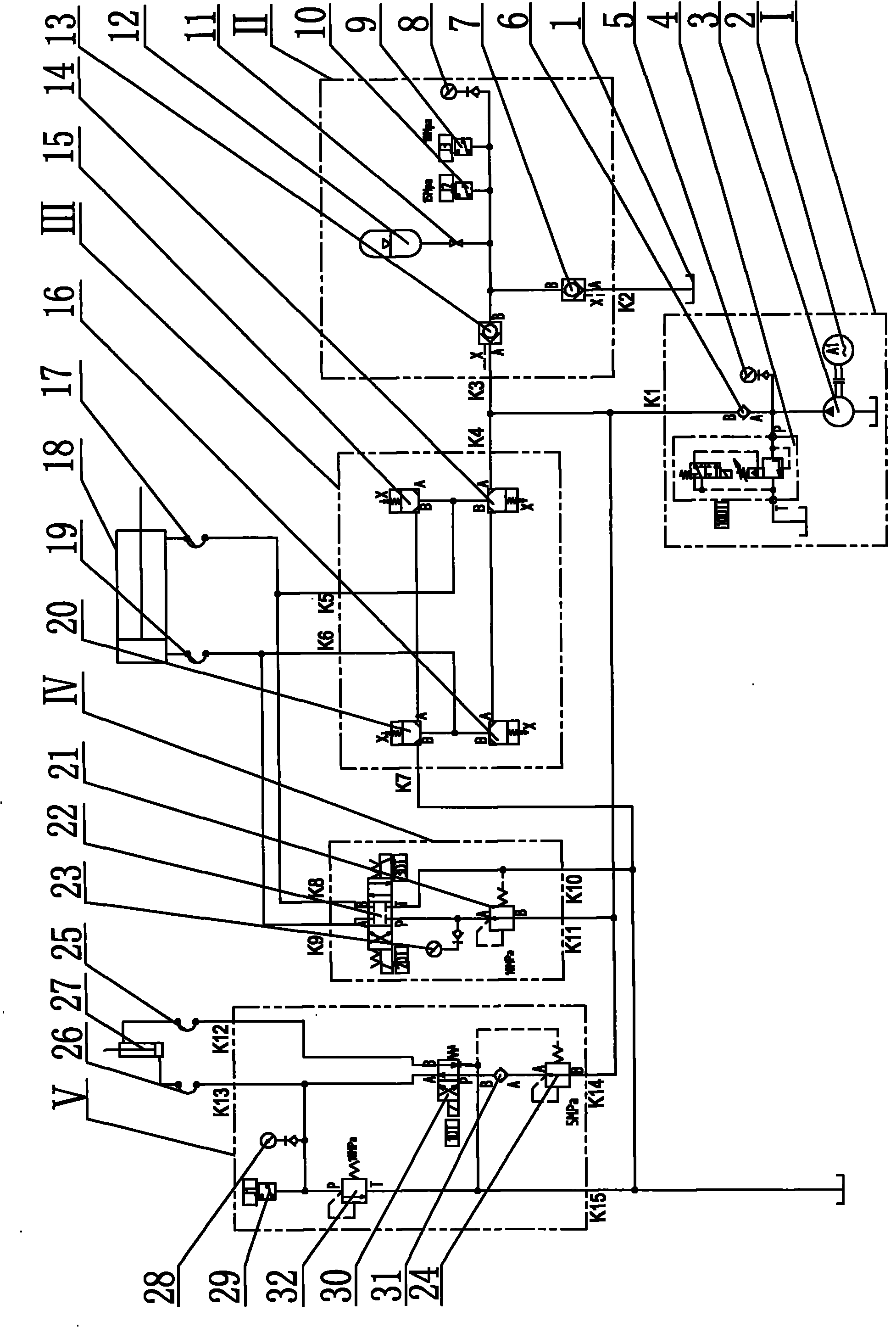
[0032] Taking the two-position four-way electromagnetic reversing valve as the pilot valve of the cartridge valve and the hydraulic control check valve as an example, its hydraulic principle is as follows: Figure 4 as shown,

[0033] A hydraulic transmission circuit for an oblique blade shearing machine, comprising a high-pressure pump source I, an accumulator control device II, a shearing cylinder control device III, a shear blade adjustment control device IV, and a platen cylinder control device V. The pressure oil port K1 of the high-pressure pump source I is respectively connected with the pressure oil port K3 of the accumulator control device II, the pressure oil port K4 of the shear cylinder control device III, the pressure oil port K11 of the shear blade adjustment control device IV and the pressure plate oil cylinder. The pressure oil port K14 of the device V is connected; the oil return port K2 of the accumulator control device II, the oil return port K7 of the shear...

Embodiment 2

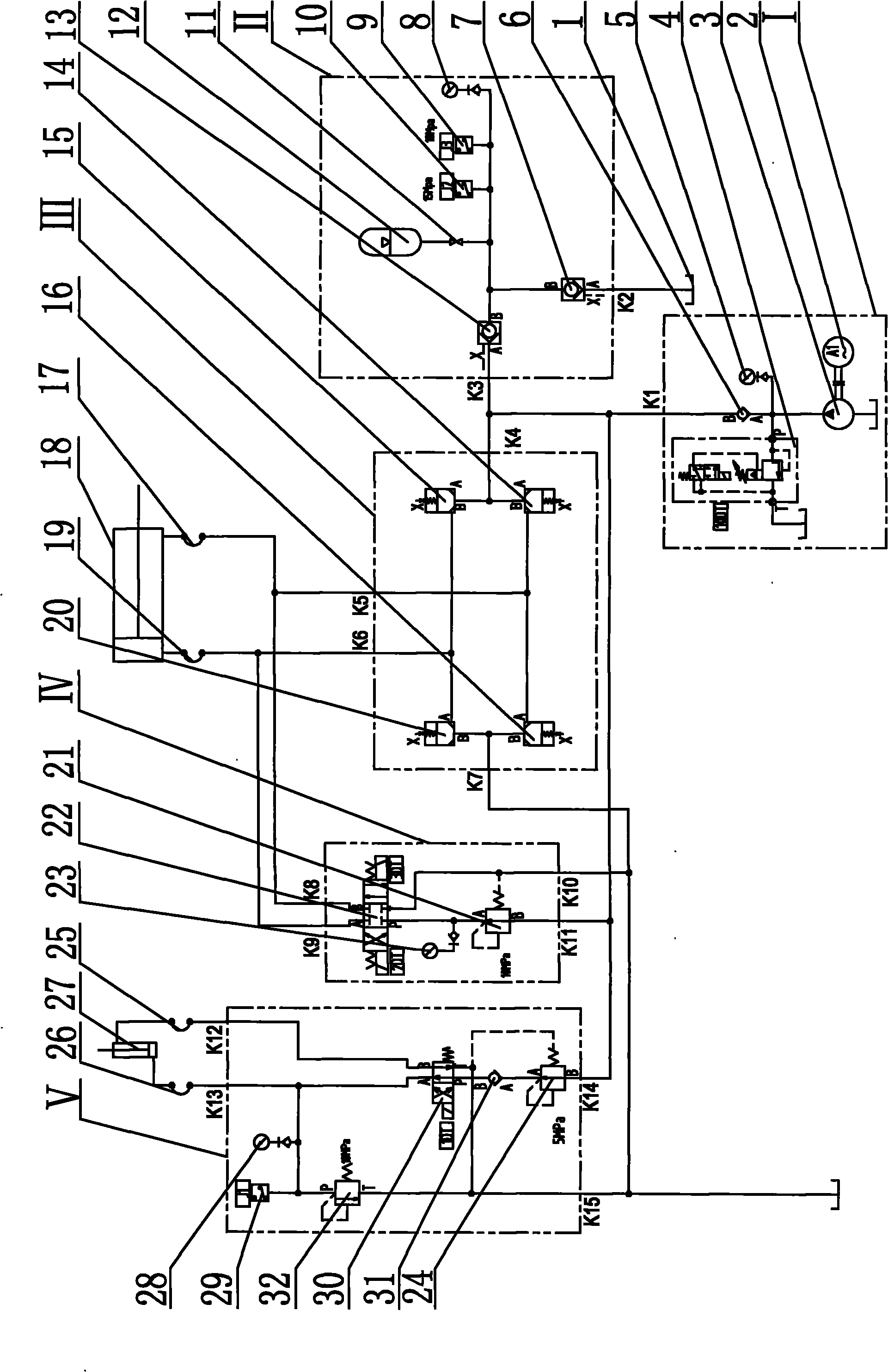
[0040] Taking the two-position four-way electromagnetic reversing valve as the pilot valve of the cartridge valve and the hydraulic control check valve as an example, its hydraulic principle is as follows: Figure 5 as shown,

[0041] The structural composition and working process of the high-pressure pump source I, the accumulator control device II, the cutting blade adjustment control device IV, and the pressure plate cylinder control device V of this embodiment are exactly the same as those of the first embodiment, and the main differences from the first embodiment are It lies in the connection mode of the shear cylinder control device III.

[0042] The connection method is: the inlet A of the fourth cartridge valve 14 is respectively connected with the working oil port K5 of the shear cylinder control device III and the inlet A of the third cartridge valve 16, and the inlet A of the first cartridge valve 20 is respectively It is connected with the working oil port K6 of t...


PUM


Abstract

The invention provides a hydraulic transmission loop of a diagonal cutter shearing machine, which belongs to the technical field of iron and steel sheet and plate processing. The invention is applicable to the hydraulic transmission of rolling production lines or experiment line shearing machines. The hydraulic transmission loop comprises a high-pressure pump source, an energy accumulator controller, a shearing oil cylinder controller, a shearing cutting edge regulation controller and a press plate oil cylinder controller, wherein a pressure oil opening K1 is respectively connected with a pressure oil opening K3, a pressure oil opening K4, a pressure oil opening K11 and a pressure oil opening K14, an oil return opening K2, an oil return opening K7, an oil return opening K10 and an oil return opening K15 are respectively connected with an oil tank, a work oil opening K6 is connected with the rod-free side of a shearing oil cylinder through a hydraulic rubber pipe, the work oil opening K5 is connected with the rod side of the shearing oil cylinder through a hydraulic rubber pipe, the work oil opening K9 is connected with the rod-free side of the shearing oil cylinder through a hydraulic rubber pipe, the work oil opening K8 is connected with the rod side of the shearing oil cylinder through a hydraulic rubber pipe, the work oil opening K13 is connected with the rod-free side of a press plate oil cylinder through a hydraulic rubber pipe, and the work oil opening K12 is connected with the rod side of the press plate oil cylinder through a hydraulic rubber pipe.

Description

Technical field: [0001] The invention belongs to the technical field of iron and steel plate processing, and in particular relates to a hydraulic transmission circuit of an oblique blade shearing machine, which is suitable for the hydraulic transmission of a rolling production line or an experimental line shearing machine. Background technique: [0002] In the strip steel production line or the strip steel test line, the shearing machine is one of the most widely used single equipment, mainly used for flattening, trimming or shearing the strip steel. The most widely used cutting machines are figure 1 In the crank slider structure shown, when the shearing cylinder is pushed out, the push rod moves forward under the drive of the shearing cylinder and drives the upper connecting rod and the lower connecting rod to move forward. At this time, the frame where the lower shearing edge is located moves upwards under the constraints of the guide rail. When the strip to be cut is pre...

Claims


Application Information

Patent Timeline
Patent Type & Authority Applications(China)
IPC IPC(8): B23D33/00F15B1/02
Inventor 王贵桥张福波
Owner NORTHEASTERN UNIV
Why Eureka
Try Eureka