Roller bed conveying line installed on portal frame

A conveyor line and gantry technology, applied in the direction of rollers, conveyors, conveyor objects, etc., can solve problems such as the inability to ensure the smooth implementation of the bogie maintenance process, and achieve the effect of large carrying capacity

Inactive Publication Date: 2011-11-23
JIANGSU SUSHENG AUTOMATION EQUIP
View PDF0 Cites 0 Cited by
  • Summary
  • Abstract
  • Description
  • Claims
  • Application Information

AI Technical Summary

Problems solved by technology

[0003] The present invention proposes a roller conveying line installed on a gantry, and its purpose is to solve the problem that "the structure of the existing new speed-raising bogies has changed greatly, and the existing maintenance equipment cannot guarantee the maintenance process of the bogies." The problem of the smooth implementation of the "smooth implementation" is adopted to change the problem of high labor intensity in the existing technology by adopting the streamlined operation mode. All process operations can be completed at one time, so as to realize the collinear automatic assembly line maintenance of various types of bogies

Method used


Image

  • Roller bed conveying line installed on portal frame
  • Roller bed conveying line installed on portal frame
  • Roller bed conveying line installed on portal frame

Examples


Embodiment

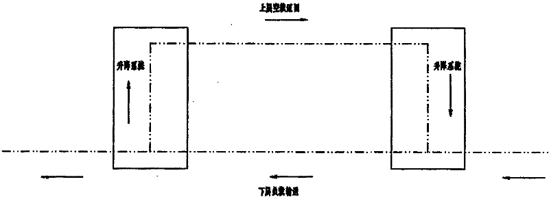
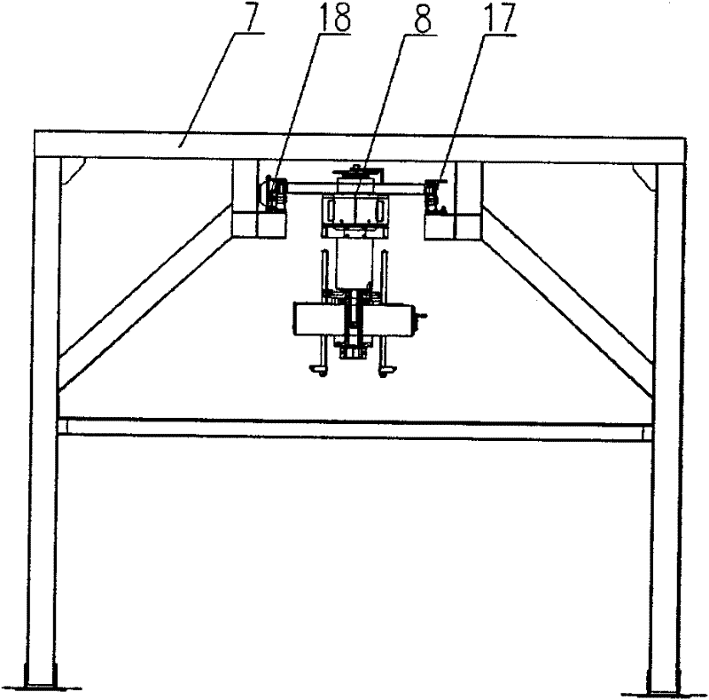
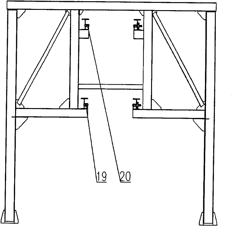
[0024] Such as figure 1 As shown, the double-dot dash line indicates the conveying line body, and the direction of the arrow indicates the conveying direction of the line body. The lower layer of the entire line body is used to transport the trolley and the workpiece with load, and the empty trolley on the upper layer returns to form a circular conveying system. The steel structure section of the single-layer roller conveyor line is as follows: figure 2 As shown, the steel structure of the double-layer roller conveyor line is as follows image 3 As shown, the connection between the single layer and the double layer is connected by a lifting system, and the top view of the lifting system is as follows Figure 5 As shown, the lifting system is composed of a steel structure and a screw lift 5, and the specific details will be described below.

[0025] The heavy-duty roller frame is installed on the gantry frame, and the trolley carrying the bogie suspension device is transport...


PUM


Abstract

The invention relates to a roller bed conveying line installed on a portal frame, which is characterized in that a roller bed frame is installed on the portal frame, a roller bed conveying line body is divided into an upper layer and a lower layer, and both ends of the line body are respectively connected by using a lifting system. An unpowered roller bed cross section, a power roller bed cross section and a friction power roller bed cross section are arranged on the roller bed frame, rollers on the unpowered roller bed cross section are unpowered rollers, rollers on the power roller bed cross section are power rollers, rollers on the friction power roller bed cross section are friction rollers, the power rollers and a plurality of unpowered rollers are installed on the roller bed frame at intervals, and the friction rollers are installed on the position to be accumulated on the line body. The roller bed conveying line has the advantages of large load bearing capability, accumulation function and networking function, can realize the collineation of multiple steering frames and one-step line-feeding accomplishment of all processing operation and the automatic line-production overhauling of the collineation of the multiple types of steering frames, provides a uniform material flow conveying platform for the overhauling of the steering frames, and is beneficial to realizing the batch production of steering overhauling complete equipment.

Description

technical field [0001] The invention relates to a roller conveyor line installed on a gantry frame, and belongs to the field of logistics conveyor equipment. Background technique [0002] When the railway and rail transit rolling stock are undergoing bogie maintenance and production processes, the two types of maintenance equipment currently used in China are basically manual. One is a mode of positioning and maintenance based on driving, supplemented by iron horses; the other is a production mode in which ground equipment is transported and fixed stations are operated by driving or cantilever cranes in conjunction with special planes. The former is the original maintenance operation mode, which uses the method of increasing the area to increase the maintenance platform to achieve the purpose of increasing the maintenance capacity; the latter has a lower degree of automation and occupies a larger area, and the use of special equipment requires driving, etc. equipment fit. ...

Claims


Application Information

Patent Timeline
Patent Type & Authority Patents(China)
IPC IPC(8): B65G37/00B65G13/00B65G47/52
Inventor 王树生
Owner JIANGSU SUSHENG AUTOMATION EQUIP
Why Eureka
Try Eureka