
Multi-angle machining type robot speed reducer shell machining equipment

A technology for reducer shells and processing equipment, which is applied in metal processing equipment, grinding/polishing equipment, manufacturing tools, etc., and can solve the problems of metal debris easily adhering to the inner wall of the shell, scratching, and affecting the machining accuracy of the shell

Pending Publication Date: 2021-07-30
昂越(上海)机械有限公司
View PDF4 Cites 0 Cited by
  • Summary
  • Abstract
  • Description
  • Claims
  • Application Information

AI Technical Summary

Problems solved by technology

[0005] The purpose of the present invention is to provide a multi-angle processing robot reducer shell processing equipment to solve the problem in the prior art that the existing equipment grinds and polishes the inner wall of the housing due to the complex structure. When polishing shells of different sizes, many parts need to be replaced; at the same time, the metal debris generated during polishing is easy to adhere to the inner wall of the shell, and it is easy to cause scratches during the clamping process of the outer ring of the new shell, and then Problems that affect the machining accuracy of the shell

Method used


Image

  • Multi-angle machining type robot speed reducer shell machining equipment
  • Multi-angle machining type robot speed reducer shell machining equipment
  • Multi-angle machining type robot speed reducer shell machining equipment

Examples


Embodiment Construction

[0028] The following will clearly and completely describe the technical solutions in the embodiments of the present invention with reference to the accompanying drawings in the embodiments of the present invention. Obviously, the described embodiments are only some, not all, embodiments of the present invention. Based on the embodiments of the present invention, all other embodiments obtained by persons of ordinary skill in the art without creative efforts fall within the protection scope of the present invention.

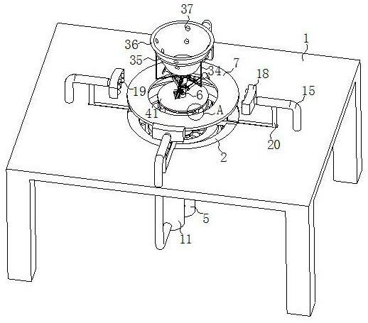
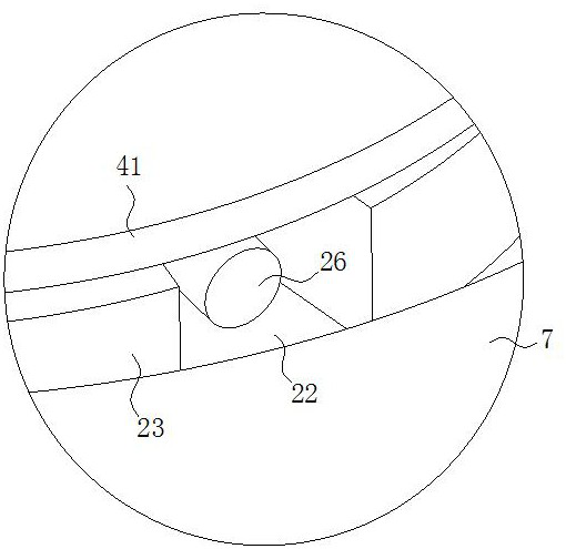
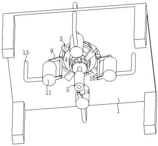
[0029] see Figure 1-9 , the present invention provides a technical solution: a multi-angle processing type robot reducer shell processing equipment, including a mounting table 1, a stepped ring groove 2 is provided in the center of the upper end surface of the mounting table 1, a fixed ring 3 is provided in the center of the mounting table 1, The fixed ring 3 is fixed on the lower end surface of the installation platform 1, and a collection mechanism is fixed insi...


PUM


Abstract

The invention discloses multi-angle machining type robot speed reducer shell machining equipment in the technical field of mechanical arms, which comprises a mounting table, a stepped ring groove is arranged in the center of the upper end face of the mounting table, a fixed ring is arranged in the center of the mounting table, the fixed ring is fixedly arranged on the lower end face of the mounting table, a collecting mechanism is fixedly arranged in the fixed ring, a motor is arranged at the lower end of the collecting mechanism, and an electric push rod is fixedly arranged at the lower end of the motor; an output shaft of the motor vertically penetrates through the collecting mechanism and is slidably arranged with the collecting mechanism, a polishing mechanism is arranged at the upper end of the collecting mechanism, a sweeping mechanism is arranged at the upper end of the polishing mechanism, a sealing mechanism is arranged at the upper end of the sweeping mechanism, and the polishing mechanism, the sweeping mechanism and the sealing mechanism are all fixedly arranged on the output shaft; and a plurality of clamping mechanisms are uniformly arranged at the outer end of the circumference of the polishing mechanism at equal angles. Through the arrangement, the problem that when existing equipment is used for grinding and polishing the inner wall of a shell, due to the complex structure, and when shells of different sizes are polished, a plurality of parts need to be replaced can be solved.

Description

technical field [0001] The invention relates to the technical field of mechanical arms, in particular to a multi-angle processing robot reducer shell processing equipment. Background technique [0002] Most of the reducers used in existing multi-angle processing robots are "RV reducers"; the RV reducer is composed of the front stage of a planetary gear reducer and the rear stage of a cycloid reducer. The RV reducer has The transmission machinery with compact structure, large transmission ratio, and self-locking function under certain conditions is one of the most commonly used reducers with small vibration, low noise and low energy consumption. [0003] In the prior art, most of the transmission mechanisms in the RV reducer are rolling transmission, but the exception is between the pin teeth and the inner wall of the housing. The actual performance is mainly sliding friction, and the force wear is similar to that of sliding bearings; in practice In the working condition, th...

Claims


Application Information

Patent Timeline
IPC IPC(8): B24B29/02B24B41/02B24B41/06B24B55/06B24B55/12
CPCB24B29/02B24B41/067B24B41/02B24B55/06B24B55/12
Inventor 葛晓敏
Owner 昂越(上海)机械有限公司
Learn More