Method and equipment for cleaning turbofan gas turbine engine

A technology for gas turbines and engines, applied to cleaning methods and appliances, cleaning methods using liquids, gas turbine devices, etc., can solve the problems of not being able to provide effective cleaning of engines, not being able to maintain manifolds with cones, and achieve lower temperatures and increased durability Sexuality and cost-saving effect

Inactive Publication Date: 2010-07-14
ECOSERVICES
View PDF8 Cites 11 Cited by
  • Summary
  • Abstract
  • Description
  • Claims
  • Application Information

AI Technical Summary

Problems solved by technology

Second, since the fans and the cones used to split the air flow are rotating, the cones cannot be used to hold the manifold
Possibly, the manifold could be mounted on a seat or rack placed upstream of the fan, but since a major part of the cleaning liquid emitted from the nozzles could impinge on the suction side of the fan blades, this configuration would not provide effective cleaning of the engine

Method used


Image

  • Method and equipment for cleaning turbofan gas turbine engine
  • Method and equipment for cleaning turbofan gas turbine engine
  • Method and equipment for cleaning turbofan gas turbine engine

Examples


Embodiment Construction

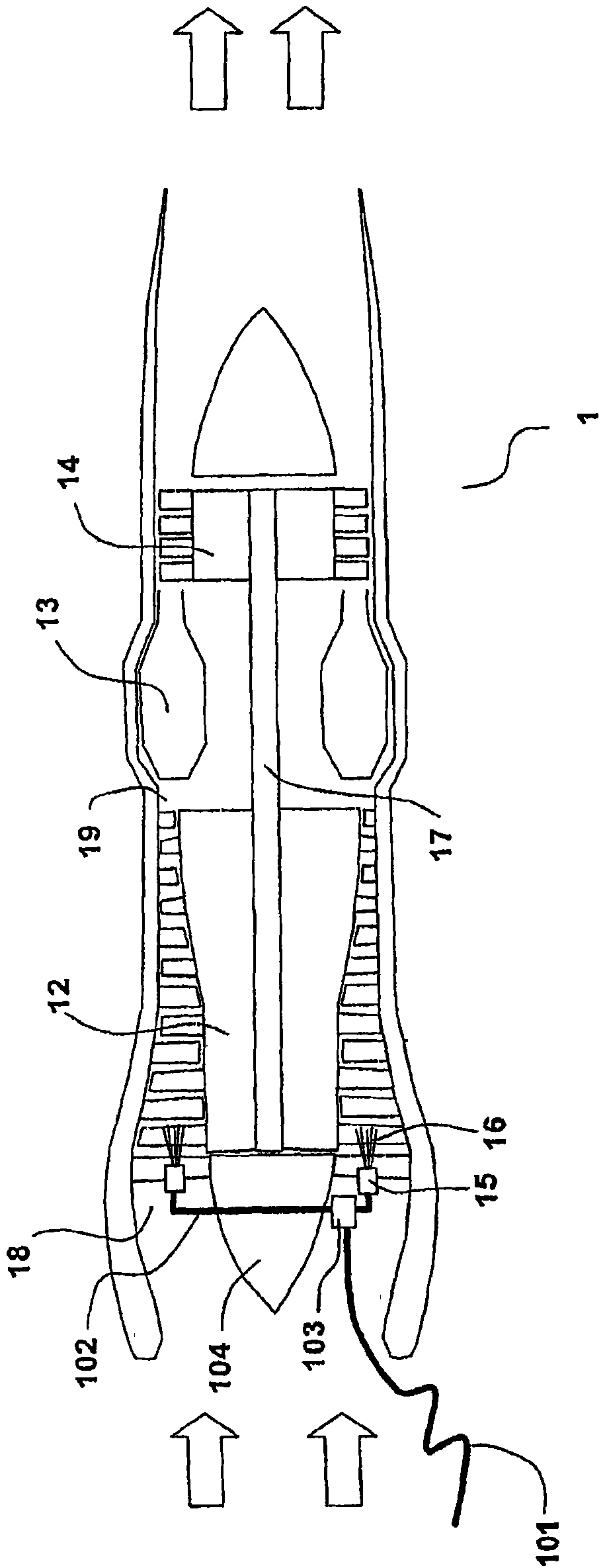
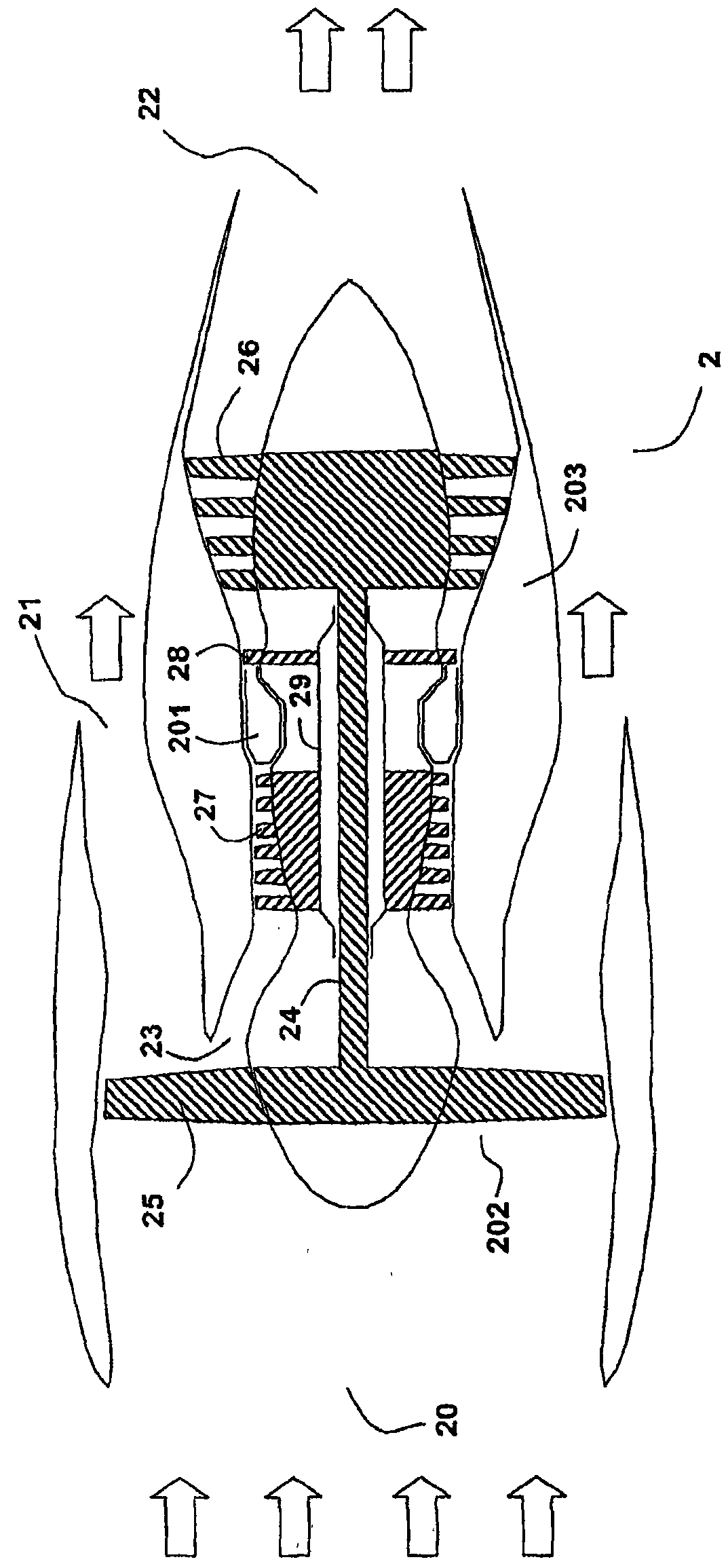
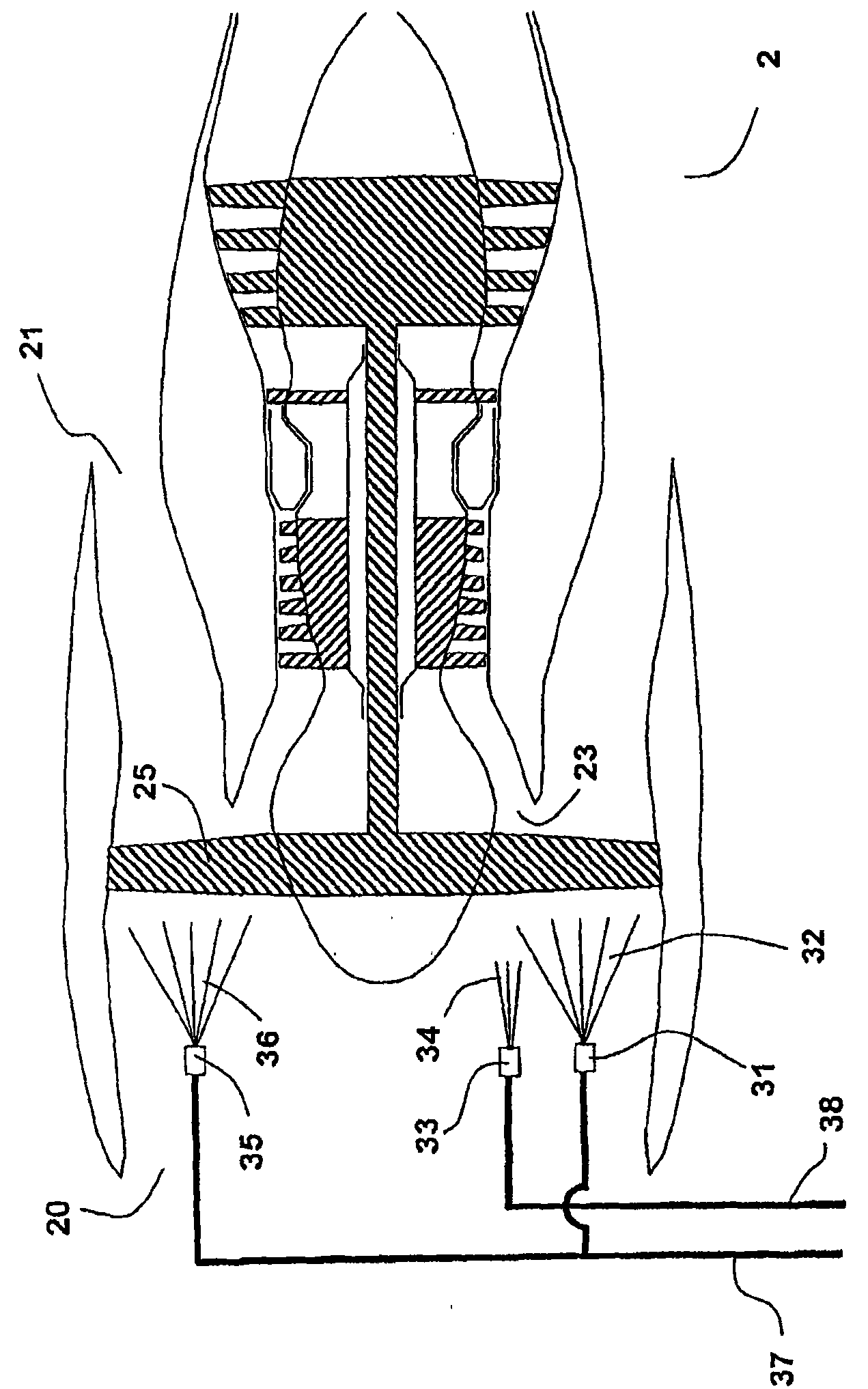
[0042] refer to figure 2 , a two-shaft non-hybrid turbofan aeroengine will be described. The twin-shaft non-hybrid turbofan engine is one of several possible turbofan engine designs. Since it is obvious that the invention can be applied to other variants of turbofan engines such as hybrid turbofan engines or turbofan engines with single, three or more shafts, this embodiment and its variants cannot be described in terms of The drawings limit the invention. A turbofan engine in which the invention is suitable for practice is characterized in that the fan and its cones for dividing the air flow are rotating.

[0043] exist figure 2 The engine 2 includes a fan unit 202 and a core engine unit 203 . The engine is built around a rotor shaft 24 which is connected at its front end to a fan 25 and at its rear end to a turbine 26 . The turbine 26 drives the fan 25 . The second axis 29 is in the form of being coaxial with the first axis 24 . At its front end a shaft 29 is connec...


PUM


Abstract

The invention relates to a device for cleaning a gas turbine engine (2), in particular for cleaning an engine of a cleaning turbine fan type. The invention also relates to a method for cleaning the engine. The device comprises a plurality of spray nozzles (31, 33, 35); and the spray nozzles (31, 33, 35) are deployed at the upstream of a fan (25) of the engine (2) and at an air inlet (20) of the engine (2) so that cleaning liquid in gas flow is atomized. According to the invention, a first spray nozzle (31) is deployed at some position, so that the cleaning liquid emitted from the first spray nozzle (31) approximately impacts the surface of a blade (40) on a pressure side (53); a second spray nozzle (35) is deployed at some position, so that the cleaning liquid emitted from the second spray nozzle (35) approximately impacts the surface of the blade (40) on a suction side (54); and a third spray nozzle (33) is deployed at some position, so that the cleaning liquid emitted form the third spray nozzle (33) approximately passes through the blade (40) and enters an inlet (23) of a core engine (203). Consequently, the invention can effectively remove different types of scale found on the fan and the core engine compressor of the turbofan engine.

Description

[0001] This application is a divisional application of a Chinese patent application filed on May 19, 2005, entitled "Method and Apparatus for Cleaning Turbofan Gas Turbine Engine" and application number 200480001287.4. technical field [0002] The present invention relates generally to the field of cleaning gas turbine engines, and more particularly to methods and apparatus for cleaning turbofan gas turbine engines installed in aircraft. Background technique [0003] A gas turbine installed as an aircraft engine includes a compressor that compresses ambient air, a combustor that burns fuel with the compressed air, and a turbine that powers the compressor. The expanding combustion gases drive the turbines and also result in the thrust used to propel the aircraft. [0004] Gas turbine engines consume large amounts of air. The air contains foreign particles in the form of aerosols that enter the gas turbine with the airflow. Most foreign particles travel along the gas path an...

Claims


Application Information

Patent Timeline
Patent Type & Authority Applications(China)
IPC IPC(8): F02B77/04B08B3/02F02C7/20
Inventor C·-J·耶普P·阿斯普伦德
Owner ECOSERVICES
Why Eureka
Try Eureka