The demand for air in these areas is very different. In the new fuel area,
oxygen is basically not needed, and only a small amount of primary air is needed to dry biomass materials;
Oxygen is supplied by the primary air, mainly by the secondary air to supply
oxygen for
combustion in the furnace; in the oxidation area, the primary air is required to supply sufficient
oxygen to cause the
combustion to release a large amount of heat violently, and to burn the
coke in the
bed material; while in the reduction The area is to reduce
carbon dioxide to
carbon monoxide and absorb heat; in the back is the
burnout area, which is mainly ash containing a small amount of unburned carbon, which requires a small amount of oxygen. It can be seen that the size of the oxidation area is critical to combustion efficiency , but under normal combustion conditions, the oxidation area is not large, especially after the grate vibrates, the new fuel area and reduction area become larger, and the oxidation area will be further reduced, so that the temperature of the grate and the
furnace temperature will also drop. When the biomass material releases a large amount of
combustible gas, and the secondary
air volume is not increased in time, a large amount of
combustible gas is wasted, which increases the chemical unburned loss of the boiler
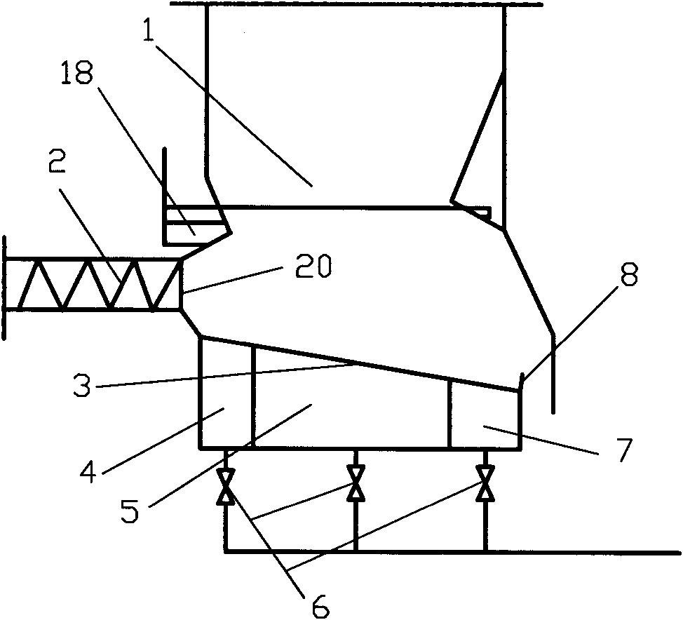
[0006] At present, the primary air chamber of the
biomass boiler with relatively
large capacity is separated according to the combustion area, as shown in the attached drawing of the manual. figure 1 As shown, it is generally divided into the first air chamber 4, the second air chamber 5 and the third air chamber 7, and the air supply is controlled respectively through the primary air control baffle 6; the primary air chamber of the relatively small
biomass boiler is not separated, and the air is supplied uniformly. In this way, the air supply cannot be differentiated according to the different air volumes required in each area, so that the combustion area (such as the oxidation area) that requires a large amount of oxygen cannot achieve the purpose of full combustion because it cannot supply sufficient oxygen, and basically does not need one time. The area where the wind supplies oxygen (new fuel area and volatile matter
precipitation area) supplies a lot of air and produces a certain amount of waste
But the problem is that even after being divided into three air chambers, the primary air in the main combustion area (such as the oxidation area) is still insufficient or the primary air cannot reach the upper position of the oxidation area on the grate, resulting in the oxidation area being too small and reducing If the area is too large, the loss of unburned
combustible gas will be large, especially when the grate is just vibrating, a large amount of new fuel will enter and spread, which will further reduce the oxidation area. At this time, the combustion state is close to the gasification process of biomass, resulting in a large amount of CO and CmHn, while the total
air volume does not increase at this time, the amount of oxygen in the supplied air cannot completely burn CO and CmHn, resulting in a significant increase in chemical incomplete combustion losses
In addition, the control baffles of the air chambers of the current biomass vibrating grate boilers have relatively poor adjustment characteristics and are prone to failure. In order to reduce the
failure rate, some biomass power plants have to remove the air intake adjustment baffles. The situation exacerbates the amount of heat loss from biomass
[0007] Through the above analysis, it can be seen that one of the main reasons for the large heat loss of the current biomass boiler is that the air supply volume does not match each combustion area, that is, the air supply cannot be differentiated according to the oxygen demand of different combustion areas; the other is that each combustion area The proportion of space actually occupied by the region is not balanced compared with the ideal state
