
Simple coordinate regulation device for regulating polarization direction of Micro-Raman spectrum system

A polarization direction and spectroscopic system technology, applied in Raman scattering, material excitation analysis, etc., can solve problems such as dust affecting accuracy and life, cumbersome polarization adjustment operations, and spectrometer damage

Inactive Publication Date: 2010-07-14
TIANJIN UNIV
View PDF0 Cites 8 Cited by
  • Summary
  • Abstract
  • Description
  • Claims
  • Application Information

AI Technical Summary

Problems solved by technology

Although this method of separate control provides the most choices of polarization configurations, the polarization adjustment operation is quite cumbersome for experimental analysis that needs to adjust the polarization directions of incident light and scattered light at any time
At the same time, since the scattered light polarization detector is generally installed inside the Raman spectrometer, the spectrometer shell needs to be opened to adjust its polarization direction, so repeated operations are easy to cause damage to the spectrometer, and the dust brought in will affect its accuracy and life.

Method used


Image

  • Simple coordinate regulation device for regulating polarization direction of Micro-Raman spectrum system
  • Simple coordinate regulation device for regulating polarization direction of Micro-Raman spectrum system
  • Simple coordinate regulation device for regulating polarization direction of Micro-Raman spectrum system

Examples


Embodiment Construction

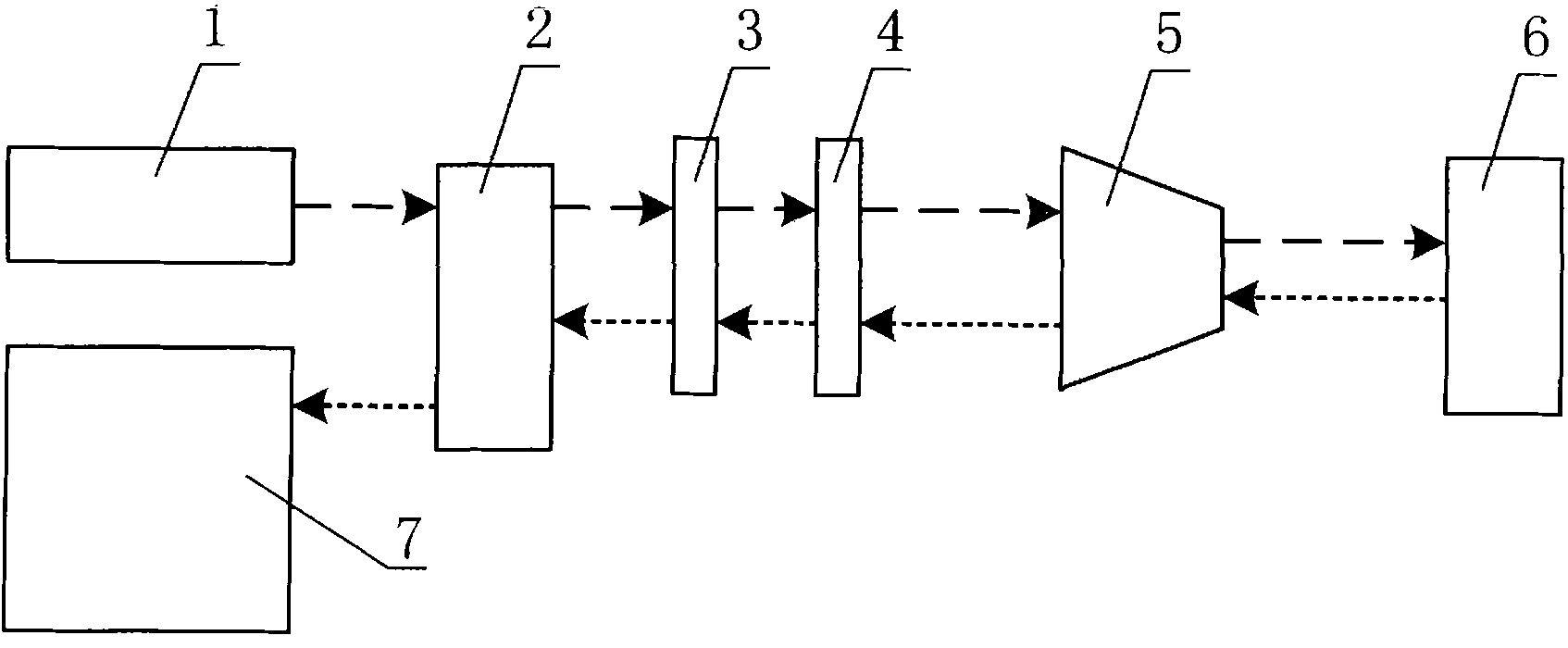
[0009] The method of the present invention will be further described below in conjunction with the accompanying drawings and through specific embodiments. A simple and coordinated adjustment device for the polarization direction of the micro-Raman spectroscopy system. Its composition is that the laser light emitted by the laser 1 sequentially passes through the incident and exit optical interface 2, the half-wave plate 3 and the polarizer 4, and then enters the surface of the measured object 6 through the microscope 5. , the backscattered light collected by the microscope 5 passes through the polarizer 4 and the half-wave plate 3 in sequence, and then enters the Raman spectrometer 7 through the incident and outgoing light interface 2 to form Raman spectrum information. The polarization adjustment component composed of the half-wave plate 3 and the polarizer 4 can also be installed between the incident and outgoing light interface 2 and the microscope 5 , or installed inside the...


PUM


Abstract

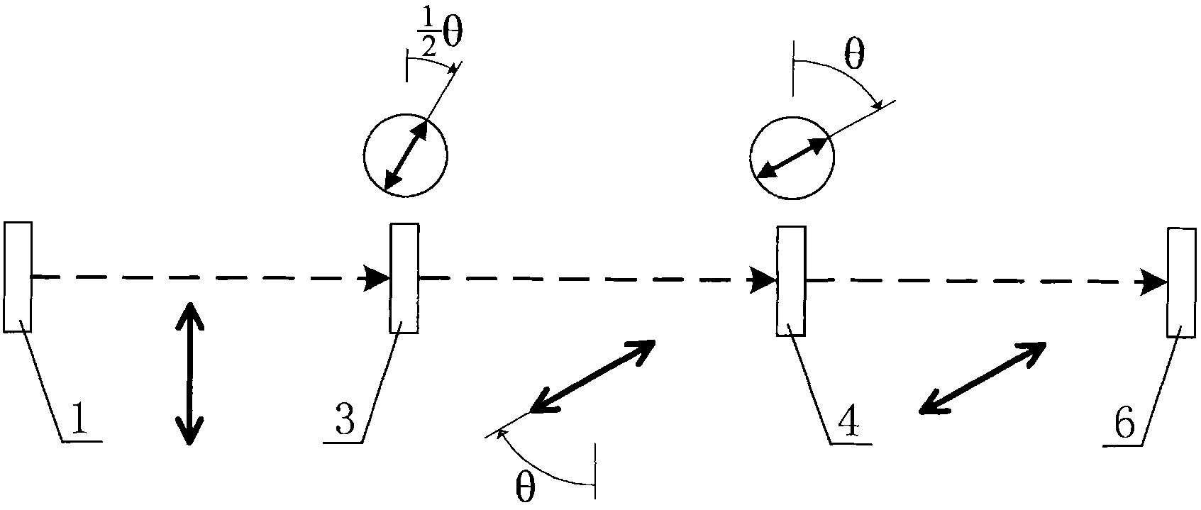
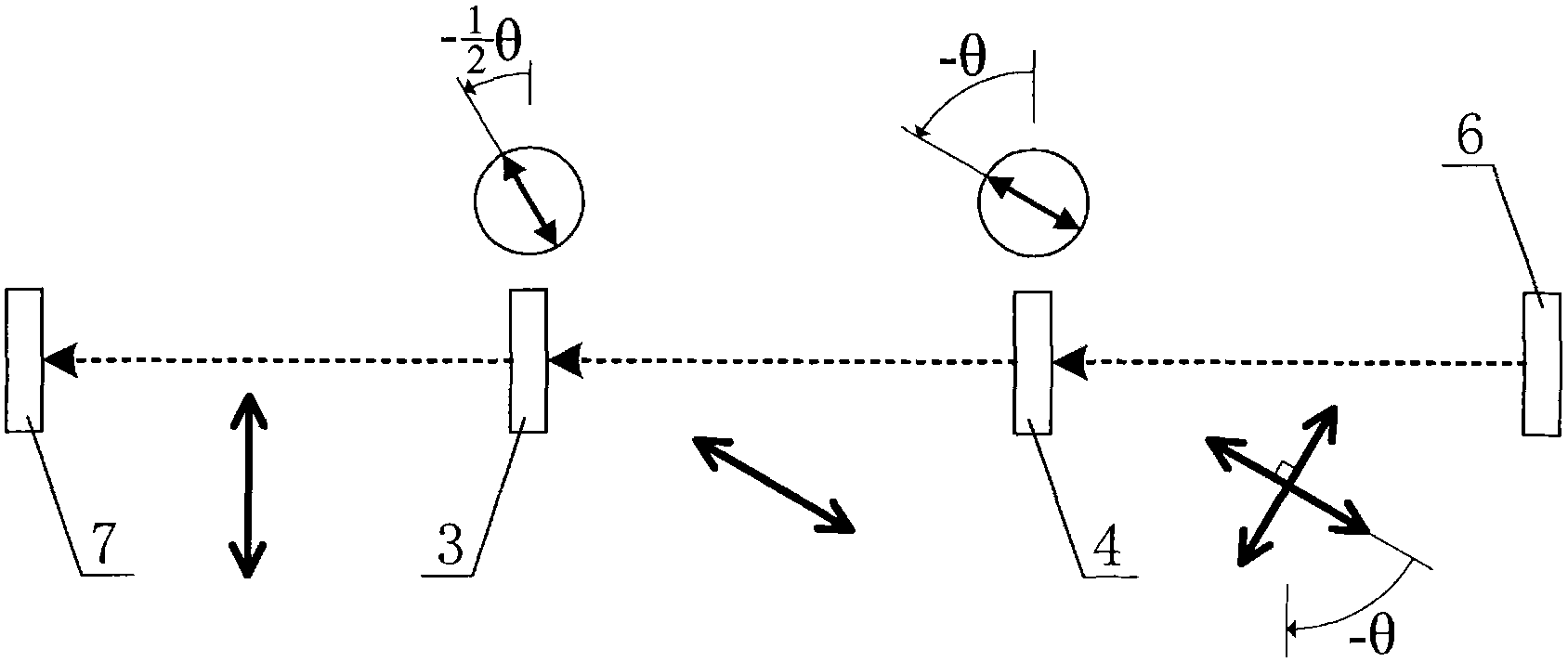
The invention discloses a technology and a device which is applied to the Micro-Raman spectrum system for simple and coordinated regulation of polarization direction of incidence light and scattered light. A laser device, an incidence and emergent light interface, a microscope and a Raman Spectrometer constitute a Micro-Raman spectrum system while a half-wave plate and a polaroid constitute a polarization regulation assembly. Laser emitted from the laser device sequentially pass through the incidence and emergent light interface, the half-wave plate and the polaroid before passing through the microscope and reaching the surface of an object to be detected.Back scattered light collected by the microscope sequentially passes through the polaroid and the half-wave plate before passing through the incidence and emergent light interface and entering the Raman Spectrometer to form spectral information. In the invention, the fast optical axis angle of the half-wave plate and polarization detection angle of the polaroid are respectively adjusted to be half of the rotation angle in the polarization direction and to be equal to the rotation angle in the polarization direction, so that coordinate regulation of polarization direction of incidence light and scattered light can be realized. In the invention, modularization of polarization control is realized, so that acquisition of the maximum grating diffraction efficiency of the scattered light entering the spectrometer can be ensured and the optimal light spectrum contrast ratio can be obtained.

Description

technical field [0001] The invention belongs to physical optics measurement technology, and in particular relates to a method and a device for adjusting the polarization direction of incident light and scattered light in a micro Raman spectrum system. Background technique [0002] As we all know, micro-Raman spectroscopy system is an experimental analysis instrument that combines modern optical microscopy technology with Raman scattering spectrometer, and is widely used in experimental analysis in many fields. Micro-Raman spectroscopy systems generally use visible, ultraviolet or near-infrared lasers as excitation light sources, and use the good polarization of lasers to analyze the Raman scattering characteristics of the research object under various configurations of the polarization directions of incident light and scattered light. An important application of micro-Raman spectroscopy system. With the continuous deepening of scientific research and engineering application...

Claims


Application Information

Patent Timeline
Patent Type & Authority Applications(China)
IPC IPC(8): G01N21/65
Inventor 仇巍亢一澜李秋雷振坤
Owner TIANJIN UNIV
Learn More