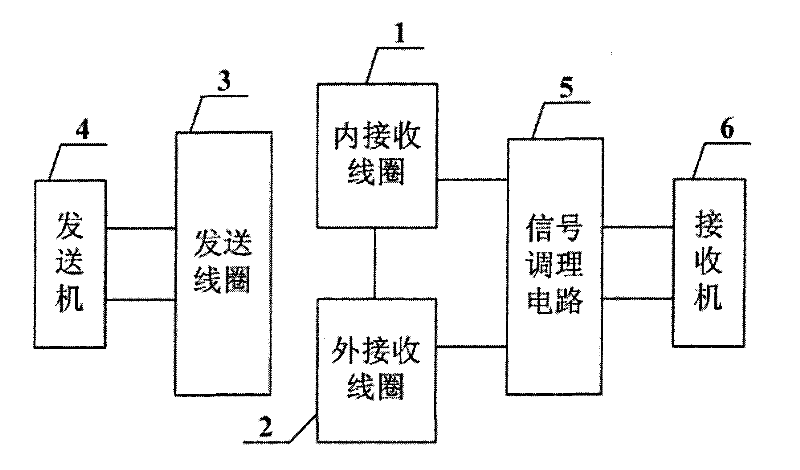
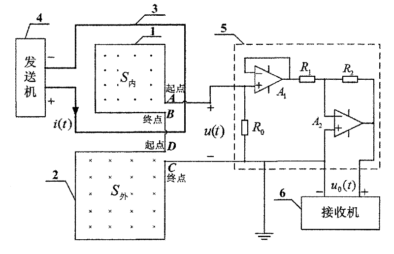
Electromagnetic prospecting sending-receiving integration method and device
An electromagnetic method and receiving coil technology, applied in the field of integration of electromagnetic transmission and inductive magnetic field detection, can solve the problems of large signal amplitude of the primary field, difficulty in distinguishing the secondary field, and existence
- Summary
- Abstract
- Description
- Claims
- Application Information
AI Technical Summary
Problems solved by technology
Method used
Image
Examples
Embodiment 1
[0155] Embodiment 1, applied to the time-domain electromagnetic method, is carried out in the following order:
[0156] 1. Design of sending coil 3, inner receiving coil 1 and outer receiving coil 2:
[0157] according to Figure 5 As shown, the center point O is selected on the plane, and the transmitting coil 3 is designed to be a planar spiral coil with 18 turns, and each turn of the coil is approximately a circle; the radius of the innermost coil is 90.875mm, the radius of the outermost coil is 150.375mm, and the line width is 2.5mm , the distance between lines is 1mm;
[0158] The inner receiving coil 1 is designed to be a 12-turn planar spiral coil, and each turn of the coil is approximately a circle; the radius of the innermost coil is 69.5mm, the radius of the outermost coil is 80.5mm, the line width is 0.5mm, and the distance between lines is 0.5mm;
[0159] The outer receiving coil 2 is designed as a fan ring composed of 16 circular arcs. The inner radius of the ou...
Embodiment 2
[0185] Embodiment 2, applied to the frequency domain electromagnetic method, is carried out according to the following sequential steps:
[0186] 1, adopt the sending coil 3 of embodiment 1 design, inner receiving coil 1 and outer receiving coil 2, get by the 2nd step of embodiment 1
[0187] ψ 内1 =2.55300×10 -5 i(t)(Wb)
[0188] Get by the 2nd step of embodiment 1
[0189] ψ 外1 =-2.55158×10 -5 i(t)(Wb);
[0190] 2. Start the transmitter, send such as Figure 9 The sinusoidal current shown, in which the current waveform is measured by the current sensor, the conversion ratio is 100mV / A, so the peak value of the current is 4.8A, and its frequency is 50Hz, which can be approximated by the sinusoidal current expression
[0191] i(t)=4.8sin(100πt)(A);
[0192] 3. Calculate the primary field induced voltage u of the inner receiving coil 1 AB1 :
[0193]
[0194] Get: u AB1 =38.5cos(100πt)(mV)
[0195] Calculate the primary field induced voltage u of the outer receiving...
Embodiment 3
[0201] Embodiment 3, applied to the time-domain electromagnetic method, is carried out in the following order:
[0202] 1. Design of sending coil 3, inner receiving coil 1 and outer receiving coil 2:
[0203] according to Figure 12 As shown, the center point O is selected on the plane, and the transmitting coil 3 is designed to be a square solenoid with 8 turns; the side length of the square is 300mm, the line width is 2mm, and the distance between lines is 3mm;
[0204] The receiving coil 1 in the design is a 6-turn square solenoid; the side length of the square is 210mm, the line width is 2mm, and the distance between lines is 1.8mm;
[0205] Design the outer receiving coil 2 to be a ring composed of 8 non-closed squares, the side length of the inner ring is 350mm, and the side length of the outer ring is 780mm; the line width is 2mm, the distance between lines is 3mm, and the separation distance is 3mm;
[0206] 2. Calculate the magnetic flux ψ passing through the inner ...
PUM
 Abstract
Description
Claims
Application Information
 - R&D
- Intellectual Property
- Life Sciences
- Materials
- Tech Scout
- Unparalleled Data Quality
- Higher Quality Content
- 60% Fewer Hallucinations
Browse by: Latest US Patents, China's latest patents, Technical Efficacy Thesaurus, Application Domain, Technology Topic, Popular Technical Reports.
© 2025 PatSnap. All rights reserved.Legal|Privacy policy|Modern Slavery Act Transparency Statement|Sitemap|About US| Contact US: help@patsnap.com


