Multiple-valued counter unit based on nerve MOS tube and multi-digit multiple-valued counter

A MOS tube and counter technology, applied in the field of multi-bit multi-value counters, can solve the problems of high cost, high power consumption, and cumbersome design of counters, and achieve the effect of saving quantity, reducing cost and power consumption

Inactive Publication Date: 2010-07-14
NINGBO UNIV
View PDF1 Cites 9 Cited by
  • Summary
  • Abstract
  • Description
  • Claims
  • Application Information

AI Technical Summary

Problems solved by technology

Traditional four-value counters are mostly implemented by four-value D flip-flops and four-value gate circuits, but these four-value components have complex struc

Method used


Image

  • Multiple-valued counter unit based on nerve MOS tube and multi-digit multiple-valued counter
  • Multiple-valued counter unit based on nerve MOS tube and multi-digit multiple-valued counter
  • Multiple-valued counter unit based on nerve MOS tube and multi-digit multiple-valued counter

Examples


Embodiment 1

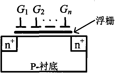
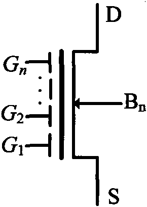
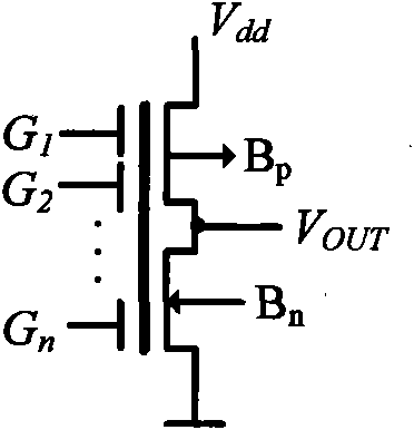
[0020] Embodiment 1: A multi-valued counter unit based on neural MOS transistors, comprising a neural MOS source follower 1 and a unit trigger circuit connected to the input control gate of the neural MOS source follower, the unit trigger circuit includes the first A binary D flip-flop 2, a second binary D flip-flop 3, an AND gate 4 and an OR gate 5, the second input terminal C of the first binary D flip-flop 2 0 and the second input C of the second binary D flip-flop 3 1 And connected to the clock signal input terminal CP, the first input terminal D of the first binary D flip-flop 2 0 and the second output terminal Q of the second binary D flip-flop 3 1 connection, the first input D of the second binary D flip-flop 3 1 and the first output terminal Q of the first binary D flip-flop 2 0 Connected to the first input terminal of OR gate 5 in parallel, the second output terminal Q of the first binary D flip-flop 2 0 And the first input terminal of AND gate 4 is connected, and...

Embodiment 2

[0021] Embodiment two: a kind of multi-bit multi-valued counter based on neural MOS tube, including two first multi-valued counter unit 10 and the second multi-valued counter unit 20 connected in series, the clock input of the second multi-valued counter unit 20 The terminal CP2 is connected with the first multi-valued counter unit 10 through an auxiliary AND gate 6, and the first multi-valued counter unit 10 includes a neural MOS source follower 11 and an input control gate connected to the neural MOS source follower. A unit trigger circuit, the unit trigger circuit includes a first binary D flip-flop 21, a second binary D flip-flop 31, an AND gate 41 and an OR gate 51, the second input terminal C of the first binary D flip-flop 21 01 and the second input terminal C of the second binary D flip-flop 31 11 And connected to the clock signal input terminal CP1, the first input terminal D of the first binary D flip-flop 2 01 and the second output terminal Q of the second binary D...


PUM


Abstract

The invention discloses a multiple-valued counter unit based on an MOS tube, which comprises a nerve MOS source electrode follower and at least one unit trigger circuit connected on an input control grid of the nerve MOS source electrode follower, wherein the unit trigger circuit comprises a first binary D flip-flop, a second binary D flip-flop, an And gate and an OR gate. The invention has the advantages that the nerve MOS tube is used to substitute for complex threshold operation in multi-valued logic, thereby realizing multi-valued logic on the true sense, the multi-valued counter with different cardinal numbers can be realized by increasing the number of the unit trigger circuit forming the binary D flip-flops and connecting the unit trigger circuit forming the binary D flip-flops with an idle input control grid of the source electrode follower. Compare with the traditional multi-valued counter, the invention can greatly save the number of the components, and reduce the cost and the energy consumption of circuit design. The invention adopts the mode of asynchronous carry to realize the multi-digit multi-valued counter on the basis of the multi-valued counter unit, and the circuit which is designed by using PSPICE simulation verification has correct logical function.

Description

technical field [0001] The invention relates to a multi-value counter, in particular to a multi-value counter unit and a multi-bit multi-value counter based on neural MOS transistors. Background technique [0002] At present, integrated circuits are developing at a speed exceeding Moore's law, and the scale of circuits that can be integrated on a chip is getting larger and faster. As a result, the power consumption of integrated circuits is increasing. The huge power consumption not only makes various portable devices encounter difficulties in power supply, but also the overheating of chips also makes them prone to work failure and shorten their lifespan. On the other hand, due to the advancement of semiconductor process technology, the area occupied by gate circuits has dropped sharply. On the contrary, in the substrate of very large scale integration (VLSI), more than 70% of the silicon area is used for wiring. Therefore, the integration degree of the circuit is limited, ...

Claims


Application Information

Patent Timeline
IPC IPC(8): G06M1/272H01L29/78
CPCH01L29/42328
Inventor 汪鹏君张跃军
Owner NINGBO UNIV
Why Eureka
Try Eureka