
Displacement estimation method of bearing-free synchronous reluctance motor, method and device for controlling displacement-free sensor

A synchronous reluctance motor, bearingless technology, applied in the direction of electronic commutator, etc., can solve the problems of increasing the moment of inertia of the motor, restricting the popularization and application of bearingless synchronous reluctance, and limiting the application

Inactive Publication Date: 2010-07-14
NANJING COLLEGE OF INFORMATION TECH
View PDF0 Cites 27 Cited by
  • Summary
  • Abstract
  • Description
  • Claims
  • Application Information

AI Technical Summary

Problems solved by technology

However, the use of displacement sensors brings many defects: on the one hand, it increases the volume of the motor, increases the moment of inertia of the motor, and restricts the maximum speed of the motor; reduces the firmness of the motor system structure, and is difficult to maintain, thus affecting the entire control system. Reliable operation, especially limits its application in harsh environments; high-precision displacement sensors are expensive, which increases the cost of the system and restricts the popularization and application of bearingless synchronous reluctance
[0004] After retrieving relevant patents and documents at home and abroad, there is no displacement sensorless control method and device for bearingless synchronous reluctance motors

Method used


Image

  • Displacement estimation method of bearing-free synchronous reluctance motor, method and device for controlling displacement-free sensor
  • Displacement estimation method of bearing-free synchronous reluctance motor, method and device for controlling displacement-free sensor
  • Displacement estimation method of bearing-free synchronous reluctance motor, method and device for controlling displacement-free sensor

Examples


Embodiment Construction

[0069] Technical scheme of the present invention is summarized as follows:

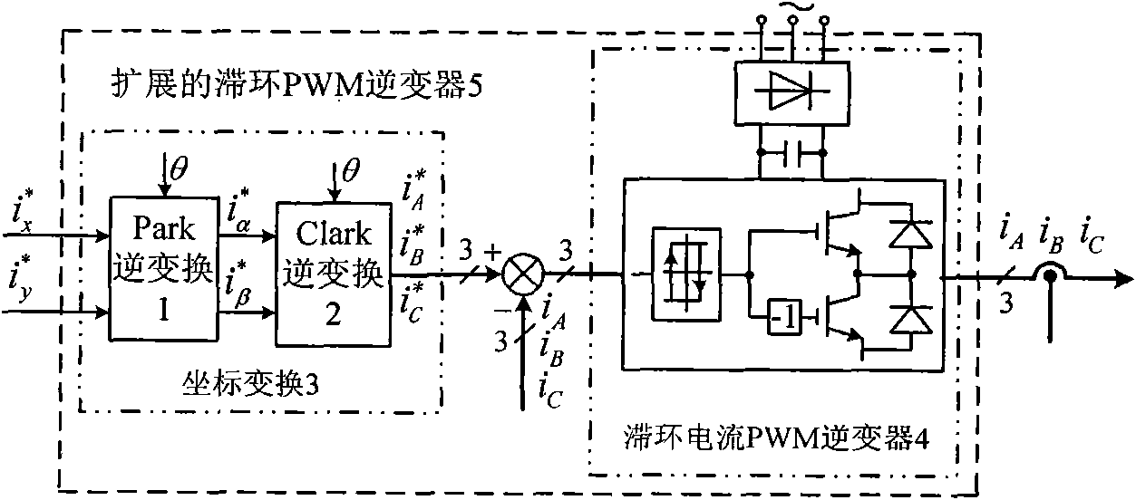
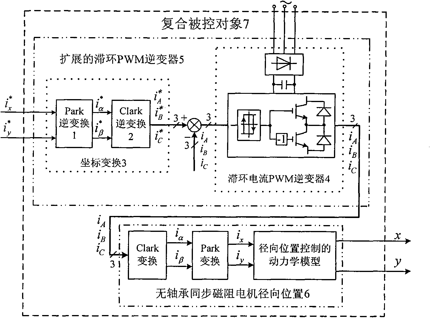
[0070]A displacement sensorless control device for a bearingless synchronous reluctance motor is constructed. The control method of the device includes the following steps: first, a hysteresis current PWM inverter, a Park inverse transform and a Clark inverse transform are used to form an extended hysteresis PWM Inverter; secondly, the radial position of the controlled bearingless synchronous reluctance motor and the extended hysteresis current PWM inverter form a compound controlled object; then the SPWM inverter that supplies power to the torque winding generates pulsating high frequency The voltage signal is injected into the torque winding of the motor; then a band-pass filter BPF is constructed, and the detection current of the suspension winding is transformed into the band-pass filter after coordinate transformation to obtain high-frequency current components; The high-frequency current compone...


PUM


Abstract

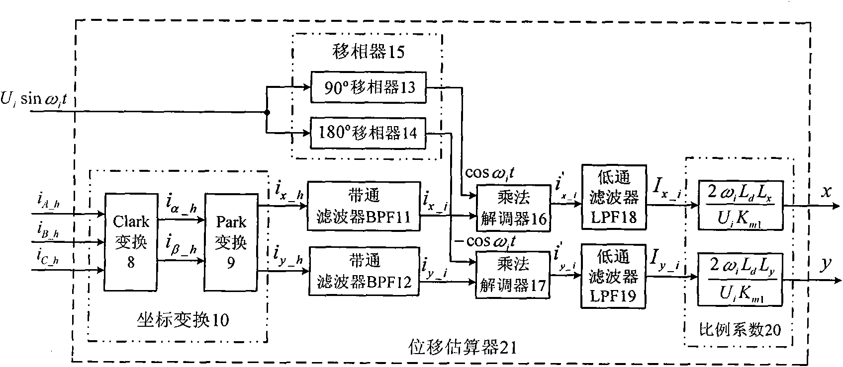
The invention relates to a displacement estimation method of a bearing-free synchronous reluctance motor, comprising the following steps: constructing a band-pass filter BPF: sending coordinate- transformed suspension winding three-phase detection current into the band-pass filter BPF; extracting suspension winding high frequency induction current ix_i and iy_i through the BPF; then constructing a multiplication demodulator: taking the ix_i and iy_i as a first input signal of the multiplication demodulator; constructing a phase shifter, taking pulsation high-frequency voltage signal ud_i having gone through phase shift as a second input signal of the multiplication demodulator; obtaining I' and I signal after demodulation computation is carried out on the two input signals by the multiplication demodulator; then filtering high-frequency component of the I' and I' signal by a low-pass filter LPF, finally obtaining current components comprising rator radial displacement; afterwards multiplying corresponding scale factor to obtain estimated value of the radial displacement of a controller electric machine rator. With the method and the device for controlling the displacement-free sensor, the displacement sensor is not needed and a DSP is adopted to control an electrical machine with the assistance of a software.

Description

technical field [0001] The invention relates to a displacement estimation method of a bearingless synchronous reluctance motor, a displacement sensorless control method and a device, which are suitable for the displacement sensorless high-performance suspension control of a bearingless synchronous reluctance motor, and belong to the technology of AC motor power transmission control equipment field. Background technique [0002] The bearingless synchronous reluctance motor is an AC motor with a novel structure. Two sets of windings with different pole pairs are embedded in the stator slot: torque winding and suspension winding. Controlling the current in these two sets of windings can not only make the motor generate Electromagnetic torque can generate radial levitation force at the same time. Therefore, it has a series of outstanding advantages: high speed, no lubrication, no wear, long life, etc., bearingless synchronous reluctance motors are used in high-speed high-precis...

Claims


Application Information

Patent Timeline
IPC IPC(8): H02P6/18
Inventor 张汉年华永平孙刚李玲张智玮
Owner NANJING COLLEGE OF INFORMATION TECH
Learn More