
Driving printed circuit board and liquid crystal display

A technology for printed circuit boards and liquid crystal displays, applied to printed circuit parts, printed circuits connected with non-printed electrical components, instruments, etc. Low-level problems, to achieve the effect of simplifying the assembly process, improving the yield rate, and simplifying the process

Inactive Publication Date: 2010-07-14
BOE TECH GRP CO LTD +1
View PDF0 Cites 13 Cited by
  • Summary
  • Abstract
  • Description
  • Claims
  • Application Information

AI Technical Summary

Problems solved by technology

In the above process, an independent step of attaching the lamp group is required. Generally, the double-sided adhesive is applied on the printed circuit board and then pasted on the backlight frame, which makes the assembly process of the backlight module complicated, and the complex process leads to High bit accuracy requirements, low assembly efficiency, and easy to produce defective products

Method used


Image

  • Driving printed circuit board and liquid crystal display
  • Driving printed circuit board and liquid crystal display
  • Driving printed circuit board and liquid crystal display

Examples


Embodiment Construction

[0022] Hereinafter, the present invention will be further described in detail through specific embodiments in conjunction with the accompanying drawings.

[0023] Drive printed circuit board embodiment

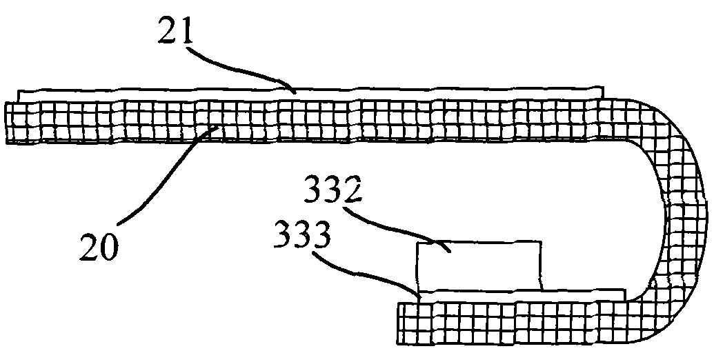
[0024] image 3 It is a schematic structural diagram of an embodiment of a driving printed circuit board of the present invention. The driving printed circuit board of this embodiment is applied to a liquid crystal display. In this embodiment, the driving printed circuit board 20 is specifically made of a flexible printed circuit board (Flexible Printed Circuit Board; hereinafter referred to as FPCB), and a liquid crystal panel driving circuit 21 and a backlight module driving are arranged on the driving printed circuit board 20. The circuit 333; the backlight module driving circuit 333 is used to mount the light source 332; when the driving printed circuit board 20 is in the assembled state, the part where the backlight module driving circuit 333 is arranged is bent into the backl...


PUM


Abstract

The invention relates to a driving printed circuit board and a liquid crystal display. The driving printed circuit board is a flexible printed circuit board on which a liquid crystal display panel driving circuit and a backlight module driving circuit are arranged; the backlight module driving circuit is used for attaching a light source; and when the driving printed circuit board is assembled, the part provided with the backlight module driving circuit is bent into a backlight module. The liquid crystal display comprises a main frame, and a liquid crystal display panel, the driving printed circuit board and the backlight module which are embedded into the main frame, wherein the driving printed circuit board is the flexible printed circuit board on which the liquid crystal display panel driving circuit and the backlight module driving circuit are arranged; the light source is attached to the backlight module driving circuit; and the part provided with the backlight module driving circuit is bent into the backlight module. The technical scheme of the invention integrates the backlight module driving circuit and the liquid crystal panel driving circuit on a printed circuit board so as to simplify the process and improve assembling efficiency.

Description

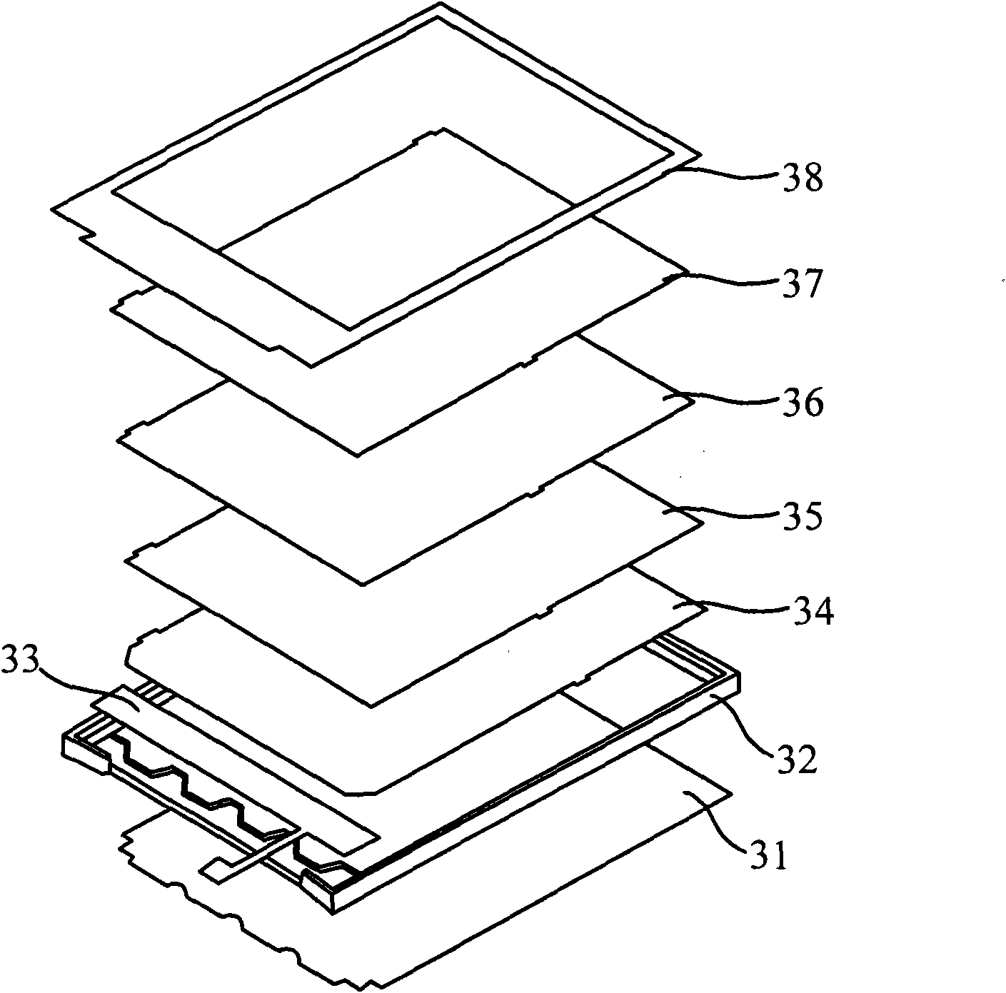
Technical field [0001] The invention relates to a backlight module structure in a liquid crystal display, in particular to a driving printed circuit board and a liquid crystal display. Background technique [0002] At present, in the flat panel display (Flat Panel Display; hereinafter referred to as: FPD) technology, the liquid crystal display (Liquid Crystal Display; hereinafter referred to as: LCD) is dominant, and the transmissive LCD is the mainstream of the current LCD technology. Since the liquid crystal itself does not emit light, the backlight module is an essential part of the transmissive LCD. [0003] Transmissive LCDs can generally be divided into side-light type and direct-light type according to the different installation positions of the backlight source. The use of side-light type backlight modules is an important means to realize LCD thinning. [0004] figure 1 Is a schematic structural diagram of an edge-lit liquid crystal display in the prior art, figure 2 It is ...

Claims


Application Information

Patent Timeline
Patent Type & Authority Applications(China)
IPC IPC(8): H05K1/02H05K1/18G02F1/13
Inventor 周振东刘飞杨东升
Owner BOE TECH GRP CO LTD
Learn More