Moisture heating tank

A heating tank and humidification technology, applied in the direction of respirators, etc., can solve the problems of water leakage, inconvenience, general products without suitable structure, etc.

Inactive Publication Date: 2010-07-21
GALEMED
View PDF0 Cites 4 Cited by
  • Summary
  • Abstract
  • Description
  • Claims
  • Application Information

AI Technical Summary

Problems solved by technology

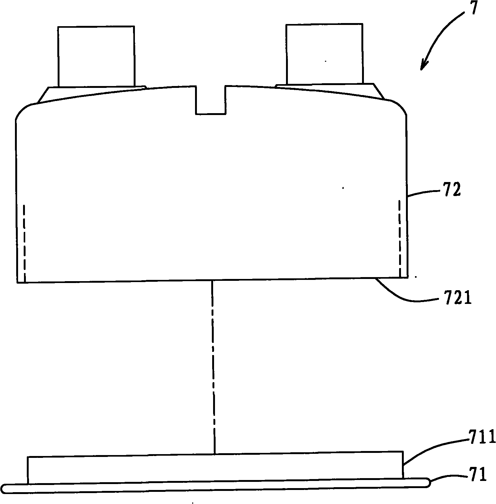
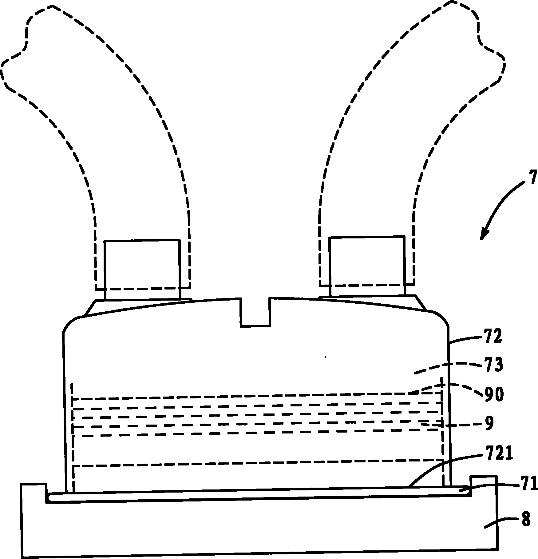
[0004] Since the engaging part 711 is located on the chassis 71 and is close to the heater 8, the rubber or plastic material of the engaging part 711 will face the problem of material fatigue in the case of repeated heating, repeated removal and fitting, and continuous cleaning and disinfection, which will cause the chassis 71 The tightness between the tank body 72 will become worse and worse, and because the water level 90 of the water body 9 is above the opening 721, the water body 9 will seep out from th

Method used


Image

  • Moisture heating tank
  • Moisture heating tank
  • Moisture heating tank

Examples


Embodiment Construction

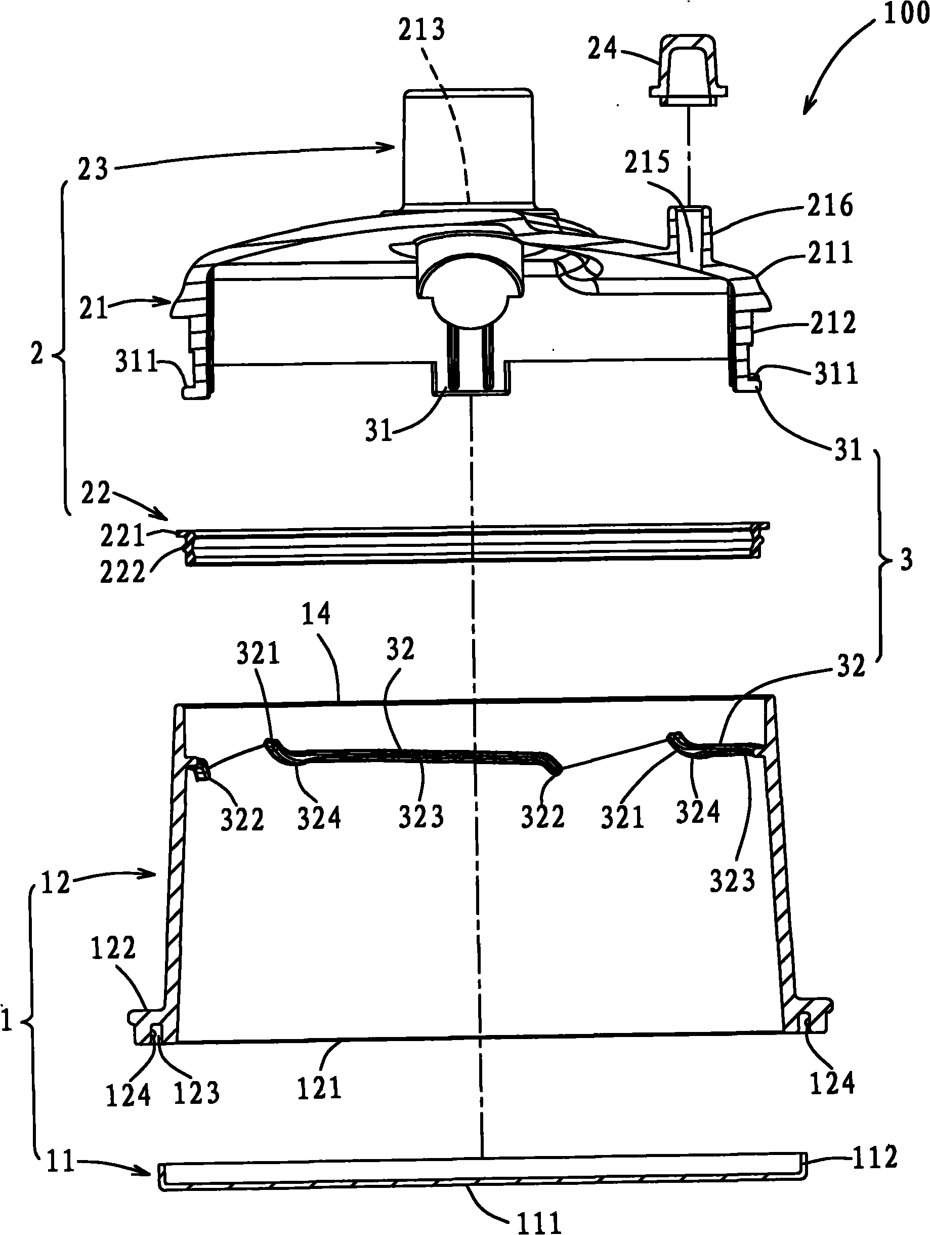
[0037]In order to further explain the technical means and effects of the present invention to achieve the intended purpose of the invention, the specific implementation, structure, characteristics and effects of the humid heating tank proposed according to the present invention will be described below in conjunction with the accompanying drawings and preferred embodiments. Details are as follows.

[0038] The aforementioned and other technical contents, features and effects of the present invention will be clearly presented in the following detailed description of preferred embodiments with reference to the drawings. Through the description of the specific implementation mode, when the technical means and functions adopted by the present invention to achieve the predetermined purpose can be obtained a deeper and more specific understanding, but the accompanying drawings are only for reference and description, and are not used to explain the present invention be restricted.

...


PUM


Abstract

The invention discloses a moisture heating tank which comprises a body, an upper cover and a sealing unit which comprises a first sealing part and a second sealing part. The body comprises a heat conduction bottom plate and a surrounding wall extending upwards from the heat conduction bottom plate, and the surrounding wall and the heat conduction bottom plate define a space and an opening arranged above the space together; the upper cover comprises a cover body which removably covers the opening, and the cover body is provided with an air inlet and an air outlet; and the first sealing part is arranged on the surrounding wall near the opening, the second sealing part is arranged on the cover body, and the first sealing part and the second sealing part can be mutually matched to enable the upper cover to tightly close the opening of the body. Preferably, the first sealing part is provided with a plurality of locking hooks, the second sealing part is provided with a plurality of locking strips, and the locking hooks and the locking strips can be respectively packed correspondingly. The invention can prevent water seepage, and the upper cover and the body can be separated and are convenient to clean. The sealing effect is achieved by utilizing the locking hooks, the locking strips and a sealing cushion. The sealing cushion is arranged far away from the heat conduction bottom plate, is not easily influenced by high temperature and can be replaced when tired.

Description

technical field [0001] The invention relates to a respiratory medical device, in particular to a reusable humid heating tank. Background technique [0002] General tracheal intubation or tracheotomy and other treatments are to establish an artificial airway bypassing the nasal cavity and upper respiratory tract to rescue and treat critically ill patients. Because the gas passes through the nasal passages and upper airway, it does not have the warming and humidifying effects of normal breathing, and humid heating canisters are usually used to do the same to keep the gas from getting too cold or too dry. [0003] see figure 1 and figure 2 as shown, figure 1 is an exploded schematic diagram illustrating an existing humid heating tank, figure 2 yes figure 1 Schematic diagram of the use state of the humid heating tank. The reusable humid heating tank 7 includes a chassis 71 for placing on a heater (warmer) 8, and a tank body 72 with an opening 721, the chassis 71 has a pl...

Claims


Application Information

Patent Timeline
IPC IPC(8): A61M16/16A61M16/10
Inventor 李清昭颜瑜倩
Owner GALEMED
Why Eureka
Try Eureka