
Oil-electric hybrid power road sweeper

An oil-electric hybrid power and road cleaning technology, applied in road cleaning, cleaning methods, construction, etc., can solve the problems of low power utilization, complex structure and high fuel consumption, and achieve the effect of improving efficiency, simplifying transmission structure and reducing fuel consumption.

Inactive Publication Date: 2010-07-21
苏州市京达环卫设备有限公司
View PDF0 Cites 13 Cited by
  • Summary
  • Abstract
  • Description
  • Claims
  • Application Information

AI Technical Summary

Problems solved by technology

[0003] At present, the existing small and medium-sized road sweepers in China can be roughly divided into three categories in terms of structural form and power configuration: one is to use the existing second-class chassis, and the walking part uses its own equipped engine to complete the walking during work, The cleaning part must be equipped with an auxiliary engine, that is, a double-engine structure with complex structure, low power utilization rate and high fuel consumption; the second type is to use the existing second-class chassis, and the travel gearbox must have a special ultra-low gear and power take-off window to complete the power configuration of the cleaning work, but the gearboxes of the existing small second-class chassis in the market do not have a power take-off window, which brings great difficulties to the design of a single-engine road sweeper; the third category is The all-electric small road sweeper is characterized by using a large-capacity battery for power supply, and the battery itself is too large. Generally, a 48V, 280AH lead-acid battery weighs about 500KG, which is too heavy. If a lithium battery is used, the battery cost will increase by more than ten times, it is obviously unbearable for users
Therefore, although the pure electric road sweeper has the advantages of environmental protection, convenient operation, and simple transmission system, its disadvantages are very obvious.

Method used


Image

  • Oil-electric hybrid power road sweeper
  • Oil-electric hybrid power road sweeper
  • Oil-electric hybrid power road sweeper

Examples


Embodiment Construction

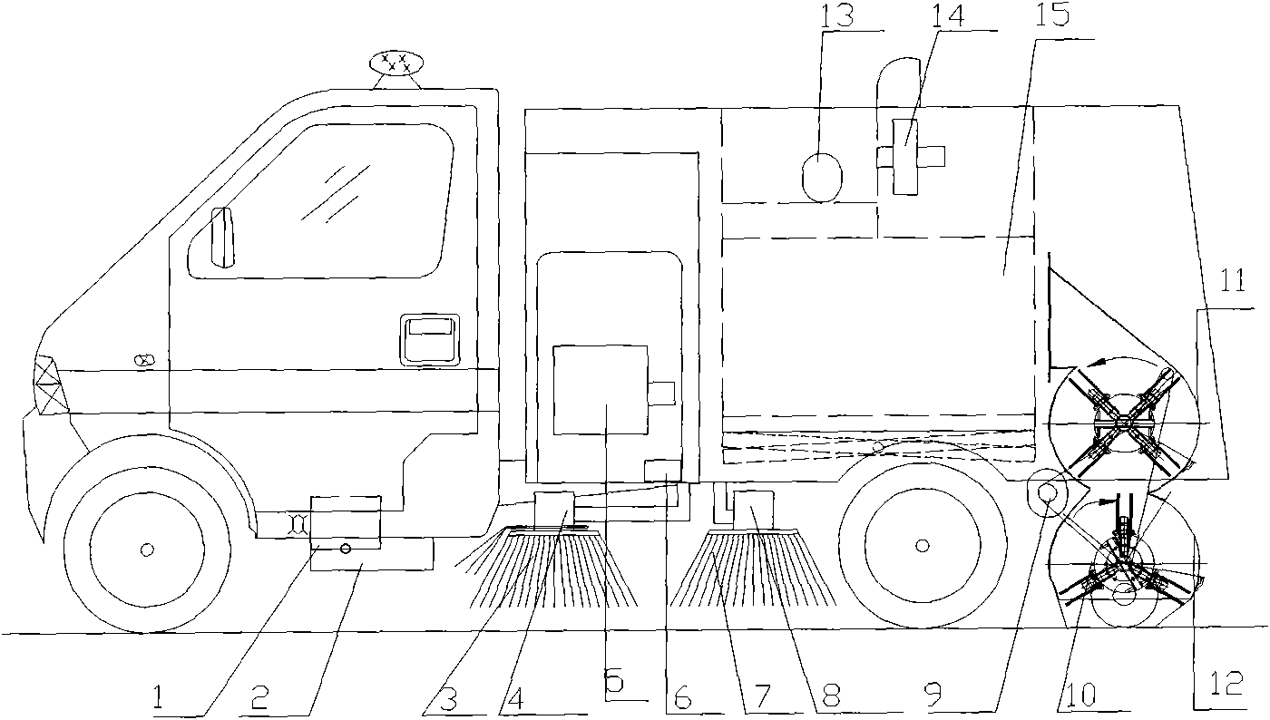
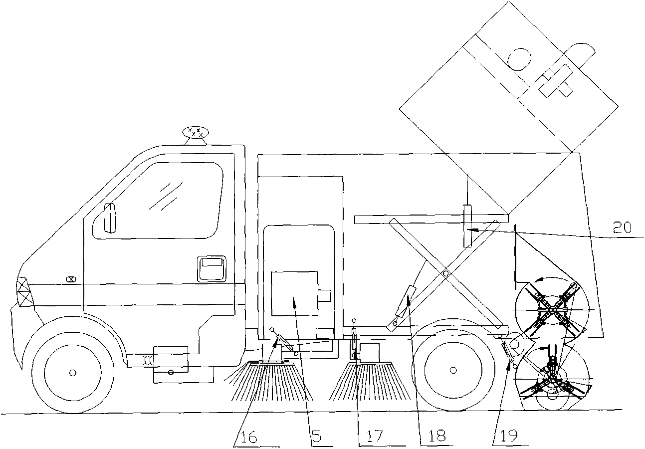
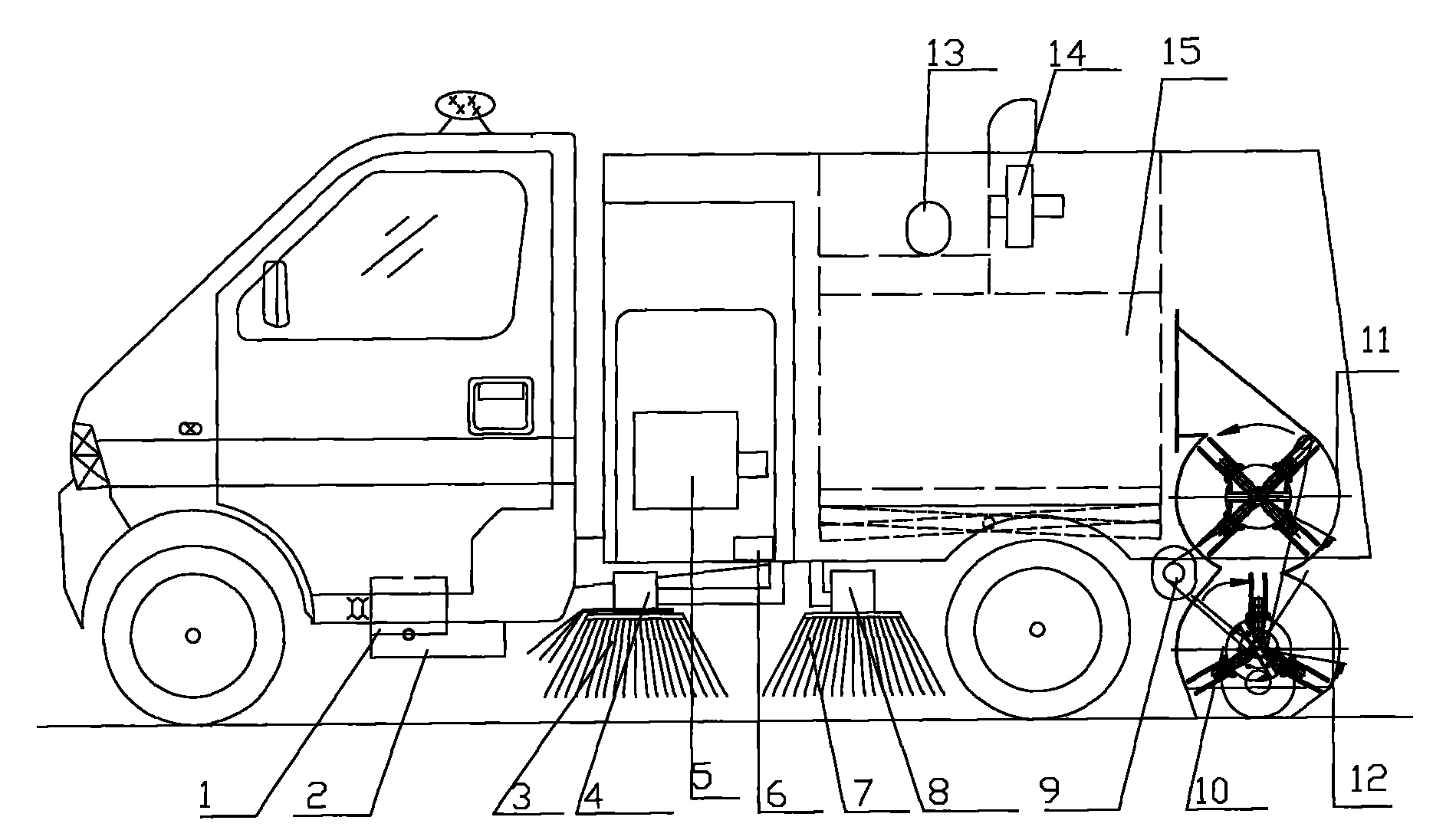
[0010] Please refer to Figure 1-2 Shown, its technical scheme mainly is made up of motor vehicle, dustbin and cleaning device. Dustbin 15 and cleaning device are installed on the motor vehicle. The motor vehicle is mainly equipped with a second-class chassis without a power take-off window of the gearbox, an engine 2 and a generator 1, the generator 1 is placed at the lower left of the front end of the engine 2, and a plurality of belt pulleys are used between the crankshaft pulley at the front end of the engine and the generator pulley. Belt drive. The generator is a 28V, 100A DC generator with a rotating speed of about 2000r / min, which not only meets the requirements of power transmission (2.4KW) and torque, but also ensures the shear and extrusion strength of the crankshaft front pulley keyway. At the same time, it also meets the bending and torsional strength requirements of the front end shaft extension of the crankshaft, thereby ensuring that the front end shaft exten...


PUM


Abstract

The invention provides a novel oil-electric hybrid power road sweeper which comprises a motor vehicle, a sweeping device and a garbage box; the motor vehicle is mainly provided with a secondary chassis with a non-power taking window gearbox, an engine and a generator arranged at the lower left part of the front end; a crankshaft pulley on the front end of the engine uses two V belts to drive a generator belt pulley; the configuration requirements of the generator are as follows: 28V, 100A DC generator, and about 2000r / min rotating speed; the sweeping device mainly comprises a double-rotating brush, a side brush, a hydraulic power unit and all oil cylinders controlled by the same and all working motors; the whole sweeping device is in electric transmission, and each motor is connected with the generator through a single circuit; and the garbage box and the sweeping device are arranged on the motor vehicle. The oil-electric hybrid power road sweeper solves an oil-electric hybrid power model which not only adopts the single engine but also adopts an electric driving system to drag a sweeping operation system.

Description

technical field [0001] The invention relates to a road cleaning tool, in particular to a road cleaning vehicle. Background technique [0002] As one of the sanitation equipment, the road sweeper is a new type of efficient cleaning equipment that integrates road cleaning, garbage, recycling and transportation. [0003] At present, the existing small and medium-sized road sweepers in China can be roughly divided into three categories in terms of structural form and power configuration: one is to use the existing second-class chassis, and the walking part uses its own equipped engine to complete the walking during work, The cleaning part must be equipped with an auxiliary engine, that is, a double-engine structure with complex structure, low power utilization rate and high fuel consumption; the second type is to use the existing second-class chassis, and the travel gearbox must have a special ultra-low gear and power take-off window to complete the power configuration of the c...

Claims


Application Information

Patent Timeline
Patent Type & Authority Applications(China)
IPC IPC(8): E01H1/05
Inventor 胡锦根
Owner 苏州市京达环卫设备有限公司
Learn More