High-voltage switch contact temperature online monitoring device and method thereof

A high-voltage switch and monitoring device technology, applied in measuring devices, thermometers, electrical devices, etc., can solve problems such as difficulty in replacement and inability to replace

Active Publication Date: 2010-07-21
常州帕斯菲克自动化技术股份有限公司
View PDF0 Cites 16 Cited by
  • Summary
  • Abstract
  • Description
  • Claims
  • Application Information

AI Technical Summary

Problems solved by technology

[0007] The power supply circuit of the transmitting part is composed of a current induction coil, an iron core of high magnetic permeability material, a voltage regulator and a filter circuit. The current induction coil is wound on the iron core of high magnetic permeability material. The ratio is determined, the iron core of high magnetic permeability material is made into a ring shape, sealed with insulating material, and then set at the position of the switch contact to be tested, so that the current induction coil will couple the large current flowing through the switch contact, and the current induction coil will output The two leads at the end are connected to the voltage conversion module, so that the transmitting part of the power supply does not need an external power supply, and uses the principle of electromagnetic field coupling to directly obtain energy from the high-voltage bus to provide power for the collector, which solves the difficulty of replacing the traditional battery power supply, which sometimes cannot be replaced. At the same time, due to the use of small CT and magnetic saturation technology, the power supply circuit of the transmitting part has achieved a wide current range of 50A-5000A, which can provide stable voltage for the microprocessor, temperature acquisition circuit and wireless transmitting circuit of the transmitting part respectively. power supply

Method used


Image

  • High-voltage switch contact temperature online monitoring device and method thereof
  • High-voltage switch contact temperature online monitoring device and method thereof
  • High-voltage switch contact temperature online monitoring device and method thereof

Examples


Embodiment Construction

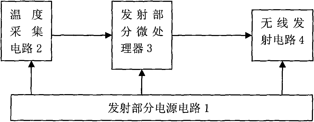
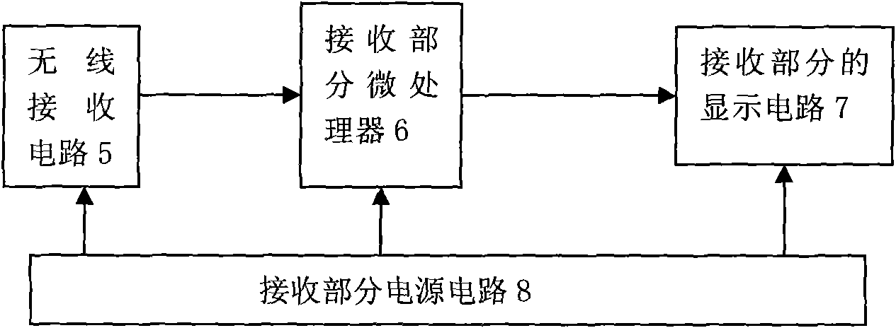
[0013] See figure 1 , figure 2 , image 3 As shown, the high-voltage switch contact temperature online monitoring device of this embodiment includes a power supply circuit of the transmitting part, a temperature acquisition circuit, a microprocessor of the transmitting part, a wireless transmitting circuit, a wireless receiving circuit, a microprocessor of the receiving part, and a The display circuit and the receiving part of the power supply circuit are composed.

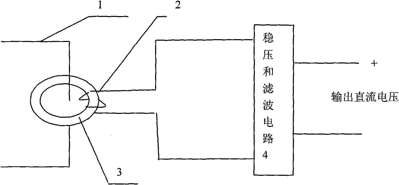
[0014] The principle of the power supply circuit of the transmitting part is as follows: image 3 As shown, it consists of a current induction coil, an iron core of high magnetic permeability material, a voltage regulator and a filter circuit. The power supply method uses the principle of electromagnetic induction, and the ferromagnetic transformer induces the AC power from the high-voltage bus, and then rectifies it. , filtering, and voltage stabilization to supply power to the high-voltage side circuit. The ...


PUM


Abstract

The invention discloses high-voltage switch contact temperature online monitoring device and method thereof. The high-voltage switch contact temperature online monitoring device comprises an emitting part power supply circuit, a temperature acquisition circuit, an emitting part microprocessor, a wireless emission circuit, a wireless receiving circuit, a receiving part microprocessor, a receiving part display circuit and a receiving part power supply circuit. When the high-voltage switch contact temperature online monitoring device is in use, the temperature acquisition part and an external power supply are not necessary to be connected, and energy is directly acquired on a high-voltage bus by utilizing an electromagnetic field coupling method to provide consistent electric energy for a collector. By adopting small CT and magnetic saturation technologies, an emitting part power supply can acquire stable voltage output in a wider current range (50-5000A). Wireless emission adopting micro-power emission with an open frequency band can not generate interference in other equipment, and a high-voltage temperature monitoring end and a display instrument end are fully separated. The temperature acquisition part of the high-voltage switch contact temperature online monitoring device is in cast with epoxy into clamp kits of different specifications so as to suit contact switches of different specifications and different shapes.

Description

technical field [0001] The invention relates to an on-line monitoring of the temperature rise of a contact point of a high-voltage switch, thereby diagnosing the failure of the high-voltage switch contact and ensuring the safe operation of the power system. Background technique [0002] In order to ensure the safe operation of the power system, the diagnosis of thermal faults in the power system is generally valued by people. When the high-voltage bus is overloaded or the contact of the high-voltage switch is not in good contact, the contact resistance will become larger and heat will be generated when the load current flows. , This heating phenomenon causes insulation aging or even breakdown, thereby causing a short circuit, forming a major accident, and causing major economic losses. [0003] In the power supply system using power cables for power transmission and distribution, statistics show that more than 90% of cable failures are caused by joint failures, and joint con...

Claims


Application Information

Patent Timeline
Patent Type & Authority Applications(China)
IPC IPC(8): G01K1/02G01K7/00G01K7/22G08C17/02G01K1/024
Inventor 周骁威
Owner 常州帕斯菲克自动化技术股份有限公司
Why Eureka
Try Eureka