Solar energy sun-following device structure

A device structure and solar energy technology, which is applied to the support structure of photovoltaic modules, photovoltaic power generation, photovoltaic modules, etc., can solve the problems of low total power generation of solar module structures and insufficient functionality, and achieve excellent functionality and high power generation. The effect of improving and improving the bending strength

Inactive Publication Date: 2010-07-21
SUNTOP SOLAR ENERGY
View PDF0 Cites 15 Cited by
  • Summary
  • Abstract
  • Description
  • Claims
  • Application Information

AI Technical Summary

Problems solved by technology

[0005] In view of the above problems, the present invention aims to improve the problems of low total power generation and insufficient functionality of the known solar module structure, and completes the solar tracking system that is easy to install and assemble, can be installed on a large scale, and effectively reduces the installation cost. Japanese device structure

Method used


Image

  • Solar energy sun-following device structure
  • Solar energy sun-following device structure
  • Solar energy sun-following device structure

Examples


Embodiment Construction

[0041] In order to further understand the structure, features and other purposes of the present invention, the following preferred embodiments are described in detail with reference to the accompanying drawings. The embodiments described in the accompanying drawings are only for the purpose of illustration, and are not intended to limit the patent application.

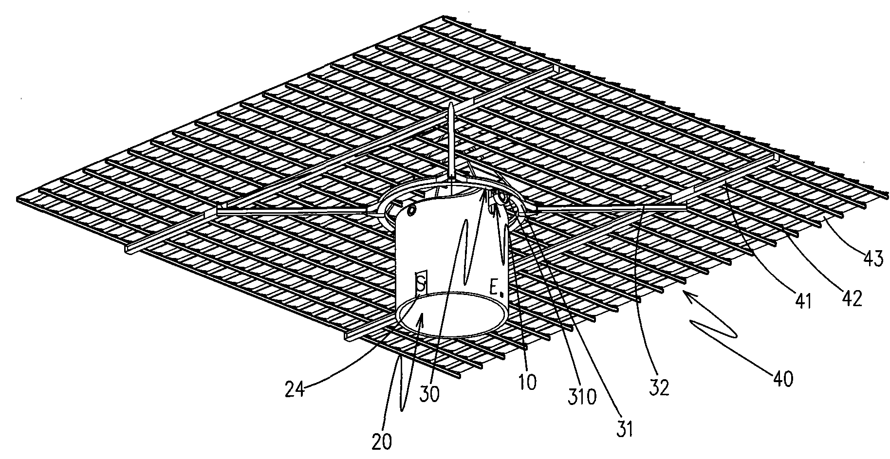
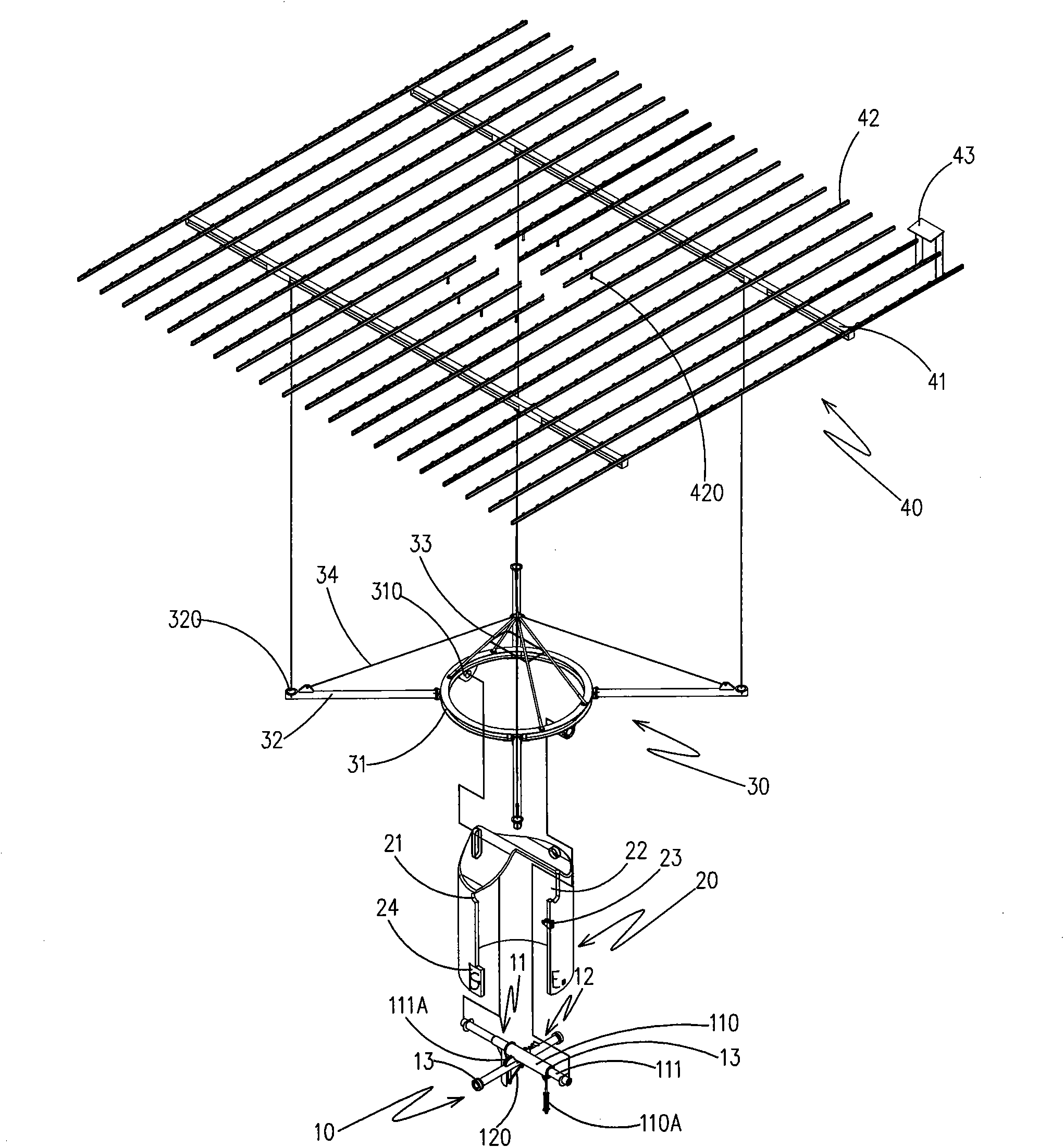
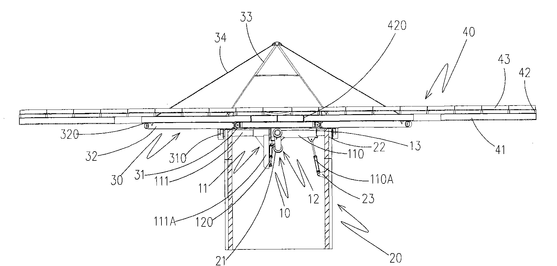
[0042] see Figure 1-5 As shown, it is a schematic diagram of the three-dimensional upward combination, three-dimensional decomposition, side view section and partial decomposition state of the structure of the solar tracking device of the present invention, which includes:

[0043] A central cross shaft group 10, the central cross shaft group 10 is provided with an east-west driving shaft body 11, a north-south driving shaft body 12 and several bearing bodies 13, and the east-west driving shaft body 11 is provided with an east-west shaft body Kit 110 and an east-west driving shaft 111, the east-west shaft kit 110 is p...


PUM


Abstract

The invention provides a solar energy sun-following device structure. An east-west driving shaft body of the solar energy sun-following device structure is in a cross connection with a north-south driving shaft body; a first driving piece arranged on an east-west shaft sleeve piece of the east-west driving shaft body is actuated to enable the north-south driving shaft body to generate east-west pivotal rotation, while a second driving piece arranged on the north-south driving shaft body is actuated to drive an east-west driving shaft piece of the east-west driving shaft body to generate south-north pivotal rotation relative to the east-west shaft sleeve piece and is linked with a cable-stayed combined annular frame body which is connected with the end of the east-west driving shaft piece, and simultaneously drives a carrier frame set connected with the cable-stayed combined annular frame to generate east-west and north-south actuation, so that a solar energy receiving module of the carrier frame set can receive solar energy by following the sun. As the volume of a base body occupies a large area, the periphery of the base body can be used for realizing subsidiary functions of parking, charging of electric vehicles and the like so that the functions of gross generation improvement and excellent use function are realized.

Description

technical field [0001] The invention relates to a structure of a solar tracking device, in particular to a multi-degree-of-freedom steering solar tracking mechanism for a solar module device that is applied to automatically change angles in pursuit of the incident angle of sunlight. Background technique [0002] With the development and changes of human civilization, the consumption of energy is increasing. However, the fossil energy (such as: oil, natural gas, coal, etc.) contained on the earth, under the extensive exploitation and use of human beings, its service life can not meet the demand , There will also be a day of exhaustion, and due to the extensive use of fossil energy, the concentration of carbon dioxide on the earth will increase, which will lead to the problem of the greenhouse effect and cause abnormal climate changes. Therefore, the world is implementing energy-saving and carbon-reducing plans. Solar energy can be said to be the largest natural energy source ...

Claims


Application Information

Patent Timeline
Patent Type & Authority Applications(China)
IPC IPC(8): H02N6/00H02S20/32
CPCY02E10/50
Inventor 李昌吉
Owner SUNTOP SOLAR ENERGY
Why Eureka
Try Eureka