Eureka AIR delivers breakthrough ideas for toughest innovation challenges, trusted by R&D personnel around the world.

Method for processing transformer pulling plate magnet isolation tank

A processing method and technology of magnetic isolation grooves, which are applied in metal processing equipment, manufacturing tools, welding equipment, etc., can solve the problems that the magnetic isolation grooves are easily cut obliquely or even cut off, and affect the quality of the pull plate, so as to avoid the need for re-calibration. The effect of low process, small investment and low processing cost

Active Publication Date: 2011-11-09
CHINA XD ELECTRIC CO LTD
View PDF0 Cites 0 Cited by
  • Summary
  • Abstract
  • Description
  • Claims
  • Application Information

AI Technical Summary

Problems solved by technology

There is also a method of underwater plasma cutting, but there is a disadvantage that the magnetic isolation groove is easy to be cut or even cut when cutting the magnetic isolation groove underwater
The above defects in the cutting method will directly affect the quality of the drawing plate

Method used


Image

  • Method for processing transformer pulling plate magnet isolation tank
  • Method for processing transformer pulling plate magnet isolation tank
  • Method for processing transformer pulling plate magnet isolation tank

Examples


Embodiment Construction

[0017] The present invention will be further described in detail below in conjunction with the accompanying drawings and embodiments.

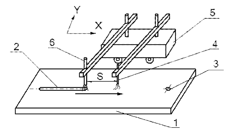
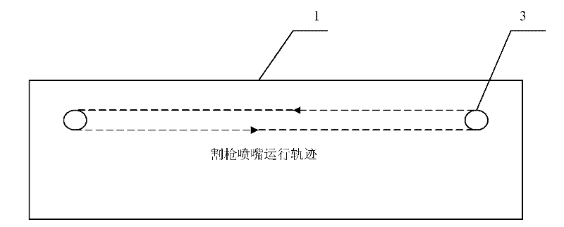
[0018] Such as figure 2 , image 3 As shown, a processing method of the magnetic isolation groove of the transformer pull plate:

[0019] In the first step, process holes 3 with a diameter of Φ10 are respectively drilled at both ends of the length of the drawing plate body 1 in the X direction.

[0020] In the second step, one end of the process hole is aligned with the nozzle of a flame torch 6 along the inside of the Y direction of the pull plate body length, and there is a cooling water pipe 4 on the same line as the flame torch 6 along the X direction; 6. The cooling water pipe 4 is connected to the moving trolley 5 on the side of the Y direction of the width of the drawing plate body 1 through two mutually parallel arms; the distance between the flame torch 6 and the cooling water pipe 4 is 50-200mm.

[0021] The third step is to turn...


PUM


Abstract

The invention discloses a method for processing a transformer pulling plate magnet isolation tank, comprising the following processing steps: first, drilling technology holes with diameter being equal to the diameter to the tank width of the magnet isolation tank at the two ends of the X direction of the length of the pulling plate body; aligning the technology holes at one end of the X directionof the length of the pulling plate body with a nozzle of a flame cutting torch along the Y direction of the width of the pulling plate body, a cooling water pipe is arranged along the X direction andat the same line the flame cutting torch is located; the flame cutting torch and the cooling water pipe are connected with a moveable cart at one side of the Y direction of the width of the pulling plate body with two mutually parallel arms; the flame cutting torch is stated to facilitate the moveable cart move along the X direction at a speed of 300-500mm / min towards the technology holes at the other end of the X direction; meanwhile, the cooling water pipe is opened to continuously inject water forward along the movement direction of the flame cutting torch; when the flame cutting torch moves to the technology holes at the other end of the pulling plate; the technology holes at the end is aligned with the nozzle of the flame cutting torch along the outside of the Y direction to facilitate the moveable cart to move in the opposite direction until the cart returns to the previous technology holes.

Description

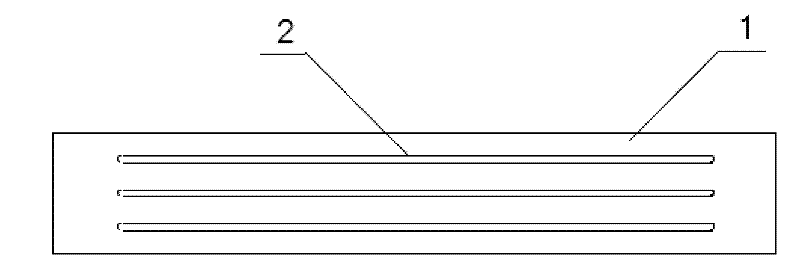
technical field [0001] The invention relates to a manufacturing method of a transformer pull plate, in particular to a processing method of a magnetic isolation groove of a transformer pull plate which prevents the deformation of cold-worked parts during the processing and affects the use. Background technique [0002] At present, there are two main types of drawing plate structures produced by transformer manufacturers: one is to use multiple narrow steel plates to form a set of drawing plates with magnetic isolation gaps; the other is to use wider steel plates by cutting long lengths between the steel plates. Slot hole (length is generally more than 2500mm, width about 10mm) to achieve the purpose of magnetic isolation. The form of transformer pull plate that cuts long slots between steel plates ( figure 1 ) is also a commonly used structural form in our company. [0003] figure 1 The drawing plate with the structure shown has a small amount of deformation when it is mac...

Claims


Application Information

Patent Timeline
Patent Type & Authority Patents(China)
IPC IPC(8): B23K7/00
Inventor 翟卫东沈维洁
Owner CHINA XD ELECTRIC CO LTD
Why Eureka
Eureka Blog
Learn More