Direct injection system in engine cavity

An engine and engine cylinder head technology, applied in the field of engine and engine combustion system manufacturing, can solve the problems of incomplete combustion of the mixture, slow combustion speed, consumption of oxygen molecules, etc. Effect

Inactive Publication Date: 2013-01-23
申阳德
View PDF0 Cites 0 Cited by
  • Summary
  • Abstract
  • Description
  • Claims
  • Application Information

AI Technical Summary

Problems solved by technology

The ignition area is small, the combustion speed is slow, and a large amount of fuel will be wasted and a large amount of oxygen molecules will be consumed during the ineffective work period of pre-ignition
Insufficient oxygen molecules will prevent the mixture from being completely combusted when the engine is working, resulting in serious exhaust pollution.

Method used


Image

  • Direct injection system in engine cavity
  • Direct injection system in engine cavity
  • Direct injection system in engine cavity

Examples


Embodiment 1

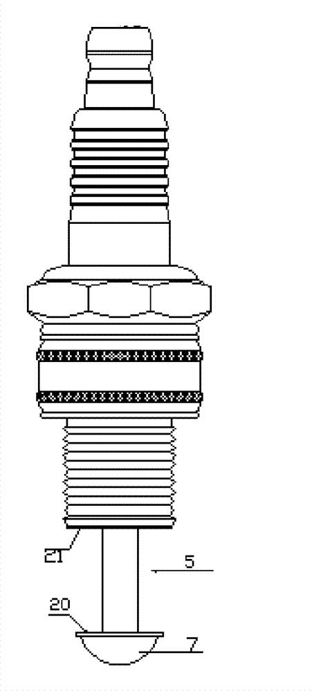
[0032] Example 1: Combining figure 1 , The flame nozzle in the figure includes a shell, which is equipped with a porcelain insulator, a double-headed screw with a wiring nut inside the porcelain insulator, a conductor glass sealant, and a center electrode extending from the porcelain insulator at one end, and a center electrode end protruding from the porcelain insulator The part is welded with the flame cap 7, wherein the flame cap 7 is a hemispherical structure, and the vertical distance between the hemispherical plane 20 and the end face 21 of the shell 3 is greater than 8 millimeters, which is 10 millimeters in this example. Wherein the central electrode only protrudes from the porcelain insulator at the part welded with the flame cap 7, and the other parts of the central electrode are wrapped by the porcelain insulator. Flame cap 7 can be the combination of hemispherical shown in the figure and a platform, also can be exactly hemispherical, also can be structures such as ...

Embodiment 2

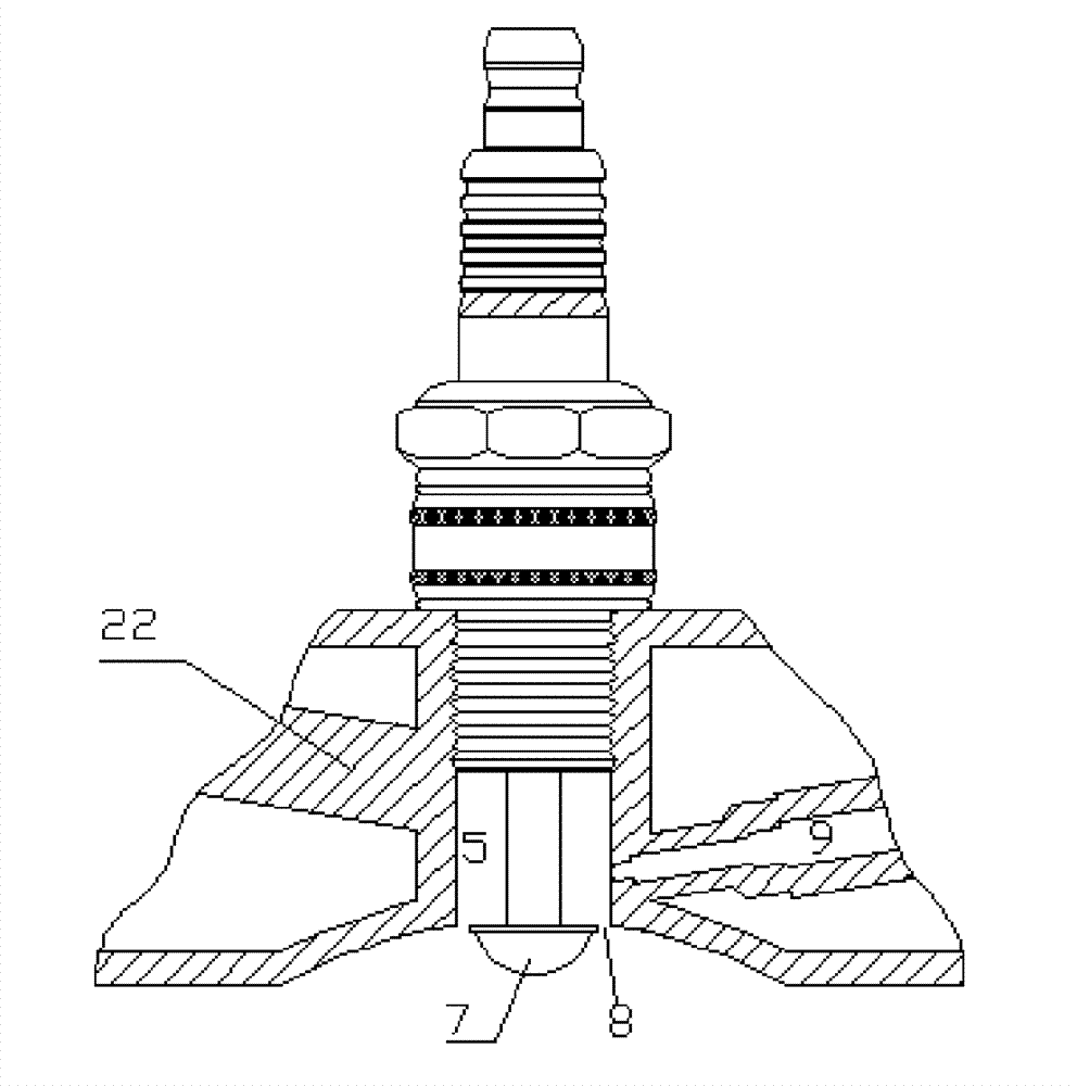
[0034] Example 2: Combining figure 2 , using the flame nozzle of the present invention on a gasoline engine, figure 2 The fuel nozzle 9 in the fuel injection chamber is in the thermal volume flame injection chamber, and it can be seen from the installation position of the gasoline fuel injection nozzle that the flame injection combustion system is composed of the main components with the flame injection nozzle as the center. The central part of the flame nozzle is designed to be installed in a small chamber in the heat volume fire chamber and exposed to the space. The entire heat volume fire chamber absorbs a large amount of heat energy, absorbing more heat and dissipating less heat to form a high-temperature hot zone, waiting for the fuel injector When the fuel is injected into the "high-temperature hot chamber" formed by the center of the flame nozzle and the cylinder head, the temperature of the fuel will suddenly rise in the hot area, and the heated fuel will become atom...

Embodiment 3

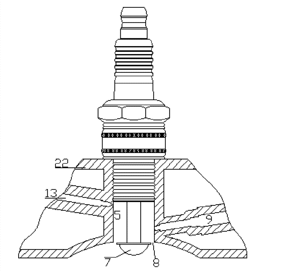
[0035] Example 3: Binding image 3 , same as embodiment 1, 2, but also have a gas spout 13 in the thermal volume flame injection chamber, the gas spout 13 can be the air spout, and the air can inject after pressurizing by the pressurizing device, the gas spout 13 can also be used as other For gas or fuel nozzles. The two nozzles have different functions in the engine. In this example: one nozzle is to inject high-pressure air to prevent the lack of oxygen molecules during high temperature and high pressure. The second injection is to inject fuel oil, which mixes high-pressure air and utilizes electric sparks to eject flames from the ignition gap and enter the combustion chamber. Gasoline nozzle 9. Gasoline is sprayed into the high-temperature small chamber. The high temperature of the central ceramic column and the flame cap heats and atomizes it. The atomized gasoline waits for the sharp corners of the edge of the flame cap and the edge of the inner hole of the cylinder head...


PUM


Abstract

The invention discloses a direct injection system in an engine cavity, which comprises an engine cylinder cover, a flame-throwing nozzle and a fuel spray nozzle, wherein the flame-throwing nozzle mainly comprises a housing, a porcelain insulator, a double-headed screw stem, a conductor glass sealant, a central electrode and a flame-throwing cap, a heat capacity flame-throwing cavity is formed by the flame-throwing cap and the engine cylinder cover, an annular ignition gap is formed by the flame-throwing cap at the end part of the heat capacity flame-throwing cavity and the engine cylinder cover, and at least one spray nozzle is arranged on the wall of the heat capacity flame-throwing cavity. One spray nozzle on the wall of the heat capacity flame-throwing cavity is the fuel spray nozzle, and another spray nozzle can be a gas spray nozzle. The direct injection system in the engine cavity has the functions of ignition, flame throwing, heating for supporting combustion and the like and can realize the reliable, uniform and rapid completion of the whole combustion process; and the addition of high pressure air can lead the combustion of an engine to be more complete. The direct injection system in the engine cavity can change the combustion way of the engine and greatly optimize and upgrade the performances of the engine.

Description

technical field [0001] The invention belongs to the field of engines, in particular to the field of engine combustion system manufacture. Background technique [0002] With the wide application of automotive engine electronic technology, electronic injection engine and direct injection engine technology are constantly developing, ordinary spark plugs can only start the ignition, and cannot achieve the effect of flame injection and combustion. Ordinary engines run fast and have slow flame spread. The engine design must determine the ignition advance angle according to the diameter of the live race, and use the ignition advance angle to make up for the time difference of slow flame propagation. The advance angle is determined by the centrifugal force of the engine rotation and the diameter of the live race. The advance angle of the live race with a diameter of 50-70 mm is about 7 degrees, and the advance angle of a live race with a diameter of 80-100 mm is about 8-12 degrees ...

Claims


Application Information

Patent Timeline
Patent Type & Authority Patents(China)
IPC IPC(8): F02B23/10
CPCY02T10/125Y02T10/12
Inventor 申阳德
Owner 申阳德
Why Eureka
Try Eureka