Eureka AIR delivers breakthrough ideas for toughest innovation challenges, trusted by R&D personnel around the world.

Method for testing corrosion behavior under thin liquid film in gas environment

A technology of metal corrosion and testing methods, applied in the direction of weather resistance/light resistance/corrosion resistance, measuring devices, instruments, etc., can solve the problems of stable control, inability to obtain the dynamic behavior of the corrosion process, lack of in-situ monitoring and tracking, etc., to achieve good stability sexual effect

Inactive Publication Date: 2010-07-28
NANCHANG HANGKONG UNIVERSITY
View PDF2 Cites 33 Cited by
  • Summary
  • Abstract
  • Description
  • Claims
  • Application Information

AI Technical Summary

Problems solved by technology

Testing the corrosion rate of materials, analyzing corrosion products, and observing surface morphology by outdoor coupons or accelerated tests are still commonly used methods to study the corrosion behavior of metal materials, but these methods are mostly ex-situ. Many important changes in the test process lack in-situ monitoring and tracking, and the dynamic behavior of the corrosion process cannot be obtained
Electrochemical methods can solve these problems very well. It can directly and deeply understand the nature of reactive corrosion, and at the same time obtain some kinetic parameters of the corrosion process. At present, the main electrochemical in-situ research methods for atmospheric corrosion mainly include atmospheric corrosion. Corrosion monitoring battery ACM, Kelvin probe reference electrode technology and reference electrode front and rear three-electrode test method, but none of them can accurately set and stably control the thickness of thin liquid film

Method used


Image

  • Method for testing corrosion behavior under thin liquid film in gas environment
  • Method for testing corrosion behavior under thin liquid film in gas environment
  • Method for testing corrosion behavior under thin liquid film in gas environment

Examples


Embodiment Construction

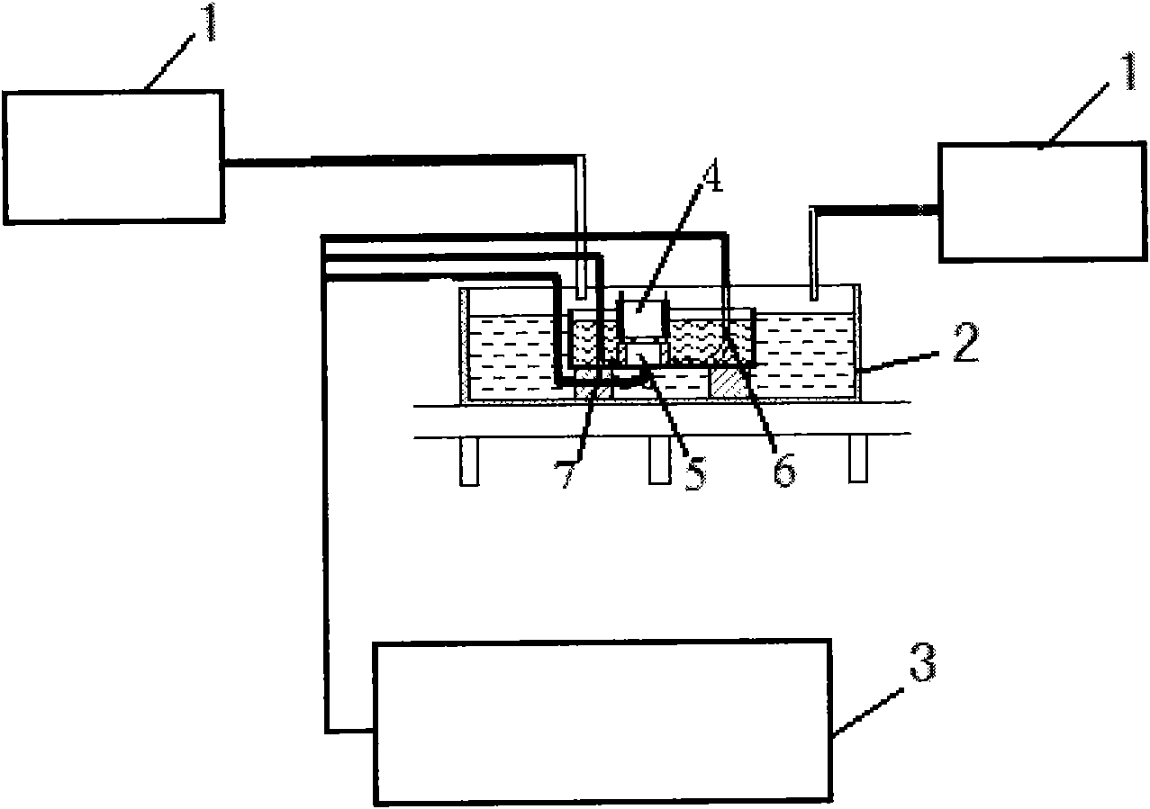
[0020] The test device consists of four parts: corrosion gas generation system 1, corrosion test box 2, thin liquid film control device 4, electrochemical workstation 3; corrosion test box 2 is made of plexiglass, the main purpose is to prevent corrosion gas from overflowing and maintain corrosion The gas concentration is within the range required by the experiment; the three electrodes and the thin liquid film thickness control system are placed in the corrosion test box 2; the thin liquid film control device 4 is composed of a bracket and a waterproof breathable membrane fixed on the end of the bracket section, There are 3 movable pillars on the bracket. During the test, the vertical distance from the top of the 3 pillars on the bracket to the waterproof and breathable membrane must be adjusted to the required length, and then the bracket is placed on the end surface of the tested metal sample 5. directly above, the vertical distance from the top of the pillar to the waterpro...


PUM


Abstract

The invention relates to a method for testing the corrosion behavior under a thin liquid film in a gas environment, which is characterized in that the method comprises the following steps that: (1) one end of a cylindrical metal sample is encapsulated with epoxy resin after being welded with a copper wire; (2) all the wires which are connected with an electrode penetrate through a corrosion test case to form small holes which are sealed by glass glue; (3) the thickness between waterproof breathable films on the bottom part of a device is controlled by setting and adjusting the thickness of the metal sample and the thin liquid film; (4) a corrosive gas is generated by using a corrosive gas generation system and is fed into a solution; (5) the corrosive gas must be always fed during the experiment process to ensure the concentration of the corrosive gas; and (6) electrochemical parameters of the metallic corrosion under the thickness of thin liquid film are obtained. The invention has the advantages that the difficulty that the thickness of the liquid film is difficult to accurately set and control is solved, the control accuracy of the think liquid film can reach plus or minus 0.5 Mum, and the method has good stability when being tested.

Description

technical field [0001] The invention relates to a method for testing the atmospheric corrosion behavior of metal materials, in particular to a method for testing the corrosion of metal materials under a thin liquid film in a gas environment. Background technique [0002] Atmospheric corrosion of materials is the most common type of corrosion, which is the result of the comprehensive action of many factors in the atmospheric environment on the surface of materials. According to statistics, the economic loss caused by atmospheric corrosion of materials accounts for more than half of the total corrosion loss. Corrosivity of materials in the atmosphere is influenced by environmental factors such as temperature, humidity and the pollutants contained in the atmosphere: SO 2 , Cl - , CO 2 , NO x Wait. With the continuous progress of society and the rapid development of economy and industry, the environmental conditions are getting worse and worse, and air pollution is becoming...

Claims


Application Information

Patent Timeline
IPC IPC(8): G01N17/02
Inventor 林翠洪昕培
Owner NANCHANG HANGKONG UNIVERSITY
Why Eureka
Eureka Blog
Learn More