Power factor corrector

A power factor correction and amplifier technology, which is used in output power conversion devices, high-efficiency power electronic conversion, electrical components, etc., to reduce switching losses and capacitive losses, and improve average efficiency.

Active Publication Date: 2010-07-28
于锁平
View PDF2 Cites 27 Cited by
  • Summary
  • Abstract
  • Description
  • Claims
  • Application Information

AI Technical Summary

Problems solved by technology

[0003] The object of the present invention is to aim at the defects of the existing continuous mode power factor corrector, to provide a continuous mode power factor corrector which adjusts the operat

Method used


Image

  • Power factor corrector
  • Power factor corrector
  • Power factor corrector

Examples


Embodiment Construction

[0015] The present invention will be further described below in conjunction with the accompanying drawings and specific embodiments.

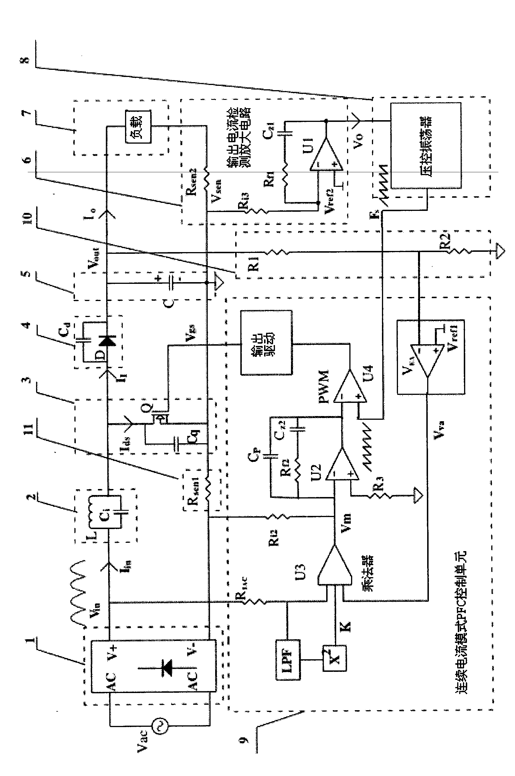
[0016] Such as figure 1 As shown, the present invention includes an input AC power supply Vac, a rectifier bridge 1, a PFC inductor 2, a switch tube 3, an output rectifier tube 4, an output filter capacitor 5, a load 7, a continuous current mode PFC control unit 9, an output voltage detection circuit 10, A current sampling resistor 11 is formed, wherein the negative pole of the output filter capacitor 5 is defined as ground. The input of the rectifier bridge 1 is connected to the AC power supply Vac, the output positive electrode of the rectifier bridge 1 is connected in series with one end of the PFC inductor 2, and the other end of the PFC inductor 2 is connected to the same point with the drain of the switch tube 3 and the anode of the output rectifier tube 4 , the source of the switch tube 3 is grounded, the gate of the switch tube 3 is co...


PUM


Abstract

The invention discloses a power factor corrector. The power factor corrector comprises an input AC power supply Vac, a rectifier bridge, a PFC inductance, a switching tube, an output rectifier tube, an output filter capacitor, a load, a continuous current mode PFC control unit, an output voltage detection circuit and a current sampling resistance; in order to enable the power factor corrector to regulate the working frequency according to the amount of output current, the circuit also comprises an output current detecting and amplifying circuit and a voltage-controlled oscillator; and the output current detecting and amplifying circuit is connected between the negative pole of the load and the negative pole of the output filter capacitor, the output end thereof is connected at the input end of the voltage-controlled oscillator, and the output end of the voltage-controlled oscillator is connected at the frequency input end of the continuous current mode PFC control unit. The working frequency of the power factor corrector is regulated by the output current, thereby reducing the switching loss and the capacitive loss of the power factor corrector under the non-full load condition, and improving the average efficiency of the power factor corrector.

Description

technical field [0001] The invention relates to a power factor corrector (PFC), in particular to a power factor corrector whose frequency is regulated by an output current, and belongs to the technical field of power electronics. Background technique [0002] The power supply of computers and communication equipment adopts traditional bridge rectification and capacitor filter circuits, which will cause serious waveform distortion of AC input current and inject a large number of high-order harmonics into the grid, so the power factor of the grid side is low, only about 0.6 , and will cause serious harmonic pollution and interference to the power grid and other electrical equipment. As early as the early 1980s, people have attracted attention to the harm caused by the high-order harmonic current generated by such devices. The formulation and implementation of the International Electrotechnical Commission IEC555-2 "Interference from Household Appliances and Similar Electrical ...

Claims


Application Information

Patent Timeline
IPC IPC(8): H02M1/42
CPCY02B70/126Y02B70/10
Inventor 于锁平
Owner 于锁平
Why Eureka
Try Eureka