Method for gasifying solid fuel and concurrent gasifier

A technology of gasification fuel and solid fuel, which is applied in gasification process, biofuel, manufacture of combustible gas, etc., to reduce the risk of fire

Inactive Publication Date: 2010-07-28
GASEK
View PDF3 Cites 4 Cited by
  • Summary
  • Abstract
  • Description
  • Claims
  • Application Information

AI Technical Summary

Problems solved by technology

The ash to be removed is hot and may contain glowing charcoal, so there is always a fire risk involved in ash removal

Method used


Image

  • Method for gasifying solid fuel and concurrent gasifier
  • Method for gasifying solid fuel and concurrent gasifier
  • Method for gasifying solid fuel and concurrent gasifier

Examples


Embodiment Construction

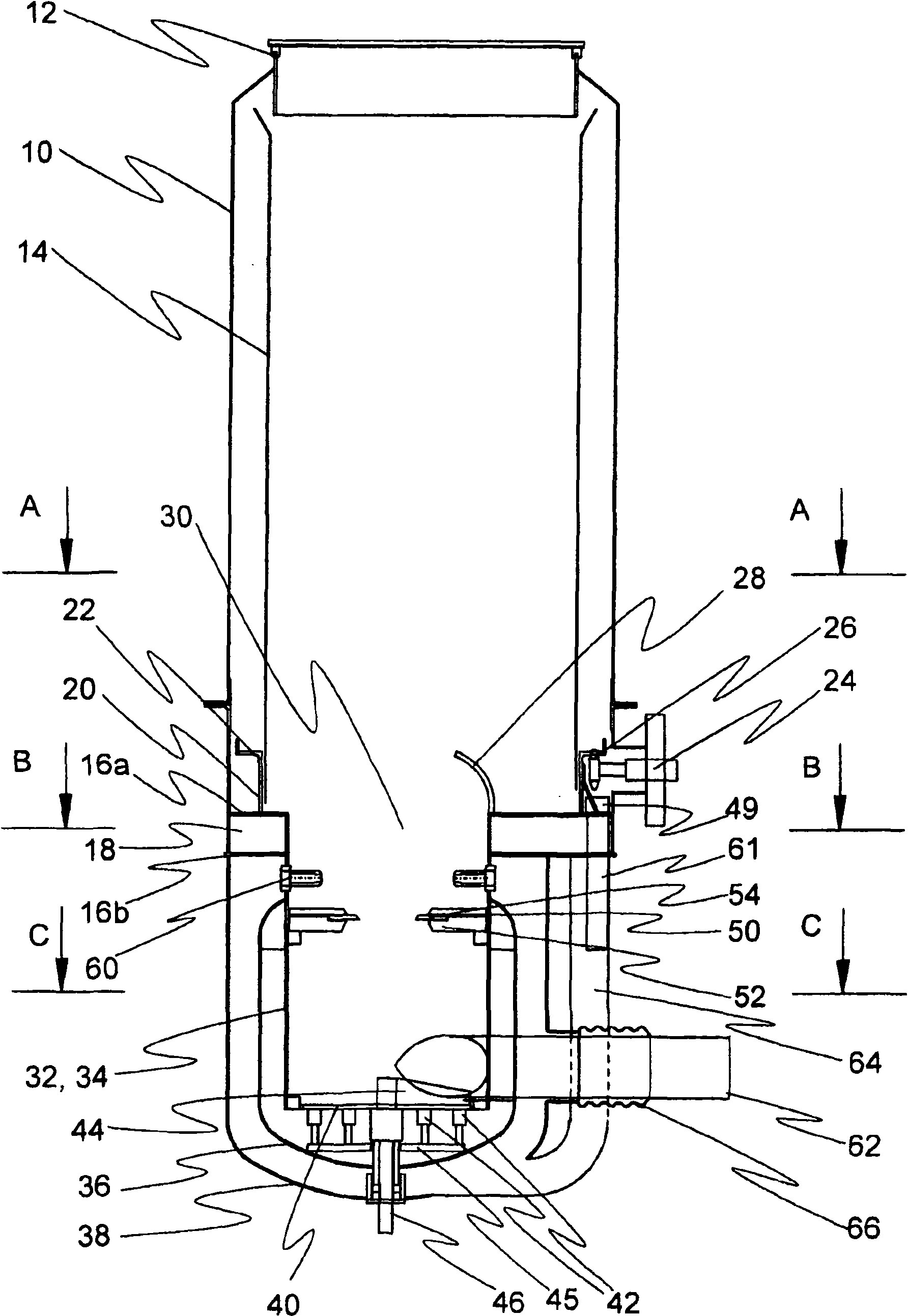
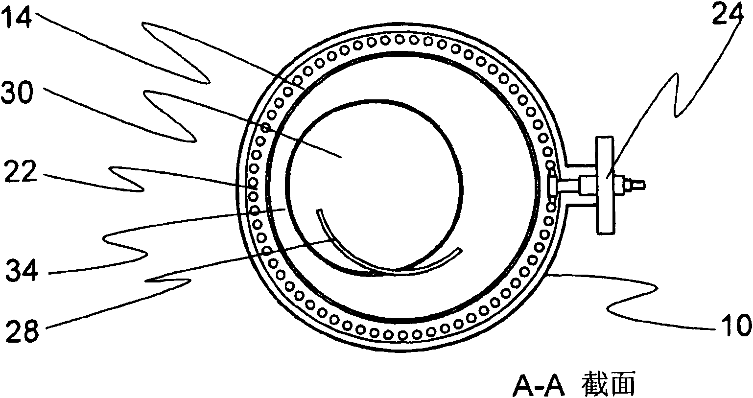
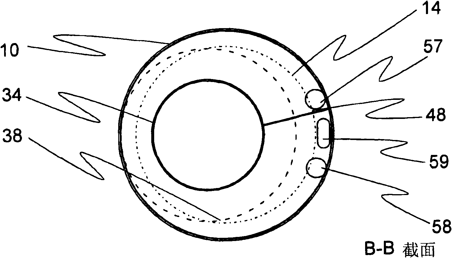
[0023] exist figure 1 In , an example of a gasification generator according to the invention is shown as a vertical section. Figure 2a to Figure 2c Shown as a horizontal section viewed along section heights A-A, B-B and C-C figure 1 vaporizer. In use, the co-flow vaporizer is at figure 1 vertical position shown. Directional expressions such as up, down, above, below, upper surface and lower surface used in this specification indicate when the gasifier is in figure 1 orientation in the vertical position shown. If the vaporizer is at a different figure 1 For some other positions than those shown, the directional expression changes accordingly.

[0024] The gasifier has a cylindrical casing 10 and on its upwardly directed end there is a gas-tight, openable cap 12 . as a basis figure 1 Instead of the cap, the gasifier may also have some other cap structure that enables automatic fueling. In the outer cover, there are two substantially parallel base plates at a certain di...


PUM

PropertyMeasurementUnit
lengthaaaaaaaaaa
diameteraaaaaaaaaa

Abstract

The invention relates to a method for gasifying solid fuel in a co-current gasifier having a fuel silo (14) and a combustion chamber (32). The method comprises a pyrolysis phase in which the fuel decomposes into pyrolysis products, and a gasification phase in which the pyrolysis products are gasified into product gas. Heat transfer from the combustion chamber (32) to the fuel silo (14) is restricted in the method. This is to ensure that the fuel does not dry and pyrolysis does not take place in the fuel silo. The beginning of the pyrolysis is intentionally transferred as close to the gasification phase as possible, and an attempt is made to make the duration of the pyrolysis phase as short as possible. The rise of the fuel temperature is slowed down by transferring heat generated in the gasification phase to a medium, such as gasification air. In the co-current gasifier according to the invention, between the fuel silo and the combustion chamber, there is a cooling channel (18), which restricts the transfer of heat and also functions as a preheater for the gasification air. The gasifier has an upper floor (16a), which forms the upper surface of the cooling channel, and a lower floor (16b) forming the lower surface of the cooling channel, and the fuel silo is placed above the upper floor and the combustion chamber below the lower floor. The combustion chamber of the gasifier comprises an internal jacket (34), an intermediate jacket (36), an external jacket (38) and a grate (40). The gasification air is arranged to be conducted to the combustion chamber through a space between the intermediate jacket and the external jacket.

Description

technical field [0001] The invention relates to a method for gasifying solid fuels, the method comprising a pyrolysis stage in which the fuel is decomposed into pyrolysis products and a gasification stage in which the pyrolysis products are gasified into product gases. The invention also relates to a co-current gasifier operated according to the method. Background technique [0002] Combustible product gases can be produced from solid fuels such as wood chips by various gasification methods. According to their operating principles, gasifiers can be classified into fixed-bed gasifiers, counter-flow gasifiers, cross-flow gasifiers, and co-flow gasifiers. Gasifiers used in co-flow gasification include vertical reactors in which fuel gasification takes place. Fuel is fed into the upper part of the reactor, from which it flows downward due to gravity. The air required in gasification is supplied to the middle of the reactor and the product gas formed is removed from the lower ...

Claims


Application Information

Patent Timeline
Patent Type & Authority Applications(China)
IPC IPC(8): C10J3/66C10J3/74C10B49/06G08B3/02
CPCY02E20/18C10J2300/0956C10J3/66C10J2300/0916C10J2200/09C10J3/26C10J2300/092Y02E50/14C10J3/80Y02E50/10C10B49/06C10G9/02C10G9/38C10J3/84C10B53/02C10J3/74
Inventor E·坎加索贾
Owner GASEK
Why Eureka
Try Eureka