Self-centering radial synchronous clamping and riveting device

A synchronous clamping and self-centering technology, applied in the direction of positioning device, clamping, support, etc., can solve the problems of insufficient clamping force, multiple driving sources, high hydraulic and electrical costs, etc., and achieve a compact structure and reasonable layout. Effect

Inactive Publication Date: 2010-08-04
HEFEI PRESSURE MACHINERY
View PDF0 Cites 10 Cited by
  • Summary
  • Abstract
  • Description
  • Claims
  • Application Information

AI Technical Summary

Problems solved by technology

[0003] To sum up, the disadvantages of synchronous movement in multiple directions above are: poor precision, insufficient clamping force, inability to self-center, and many driving sources. Multi-directional clamping requires the support of multiple

Method used


Image

  • Self-centering radial synchronous clamping and riveting device
  • Self-centering radial synchronous clamping and riveting device
  • Self-centering radial synchronous clamping and riveting device

Examples


specific Embodiment approach

[0018] The specific implementation, non-limiting examples are as follows:

Embodiment

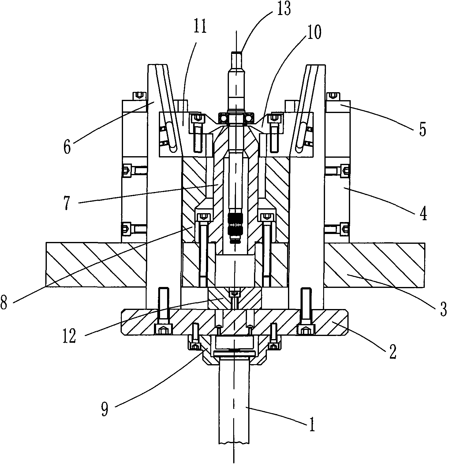
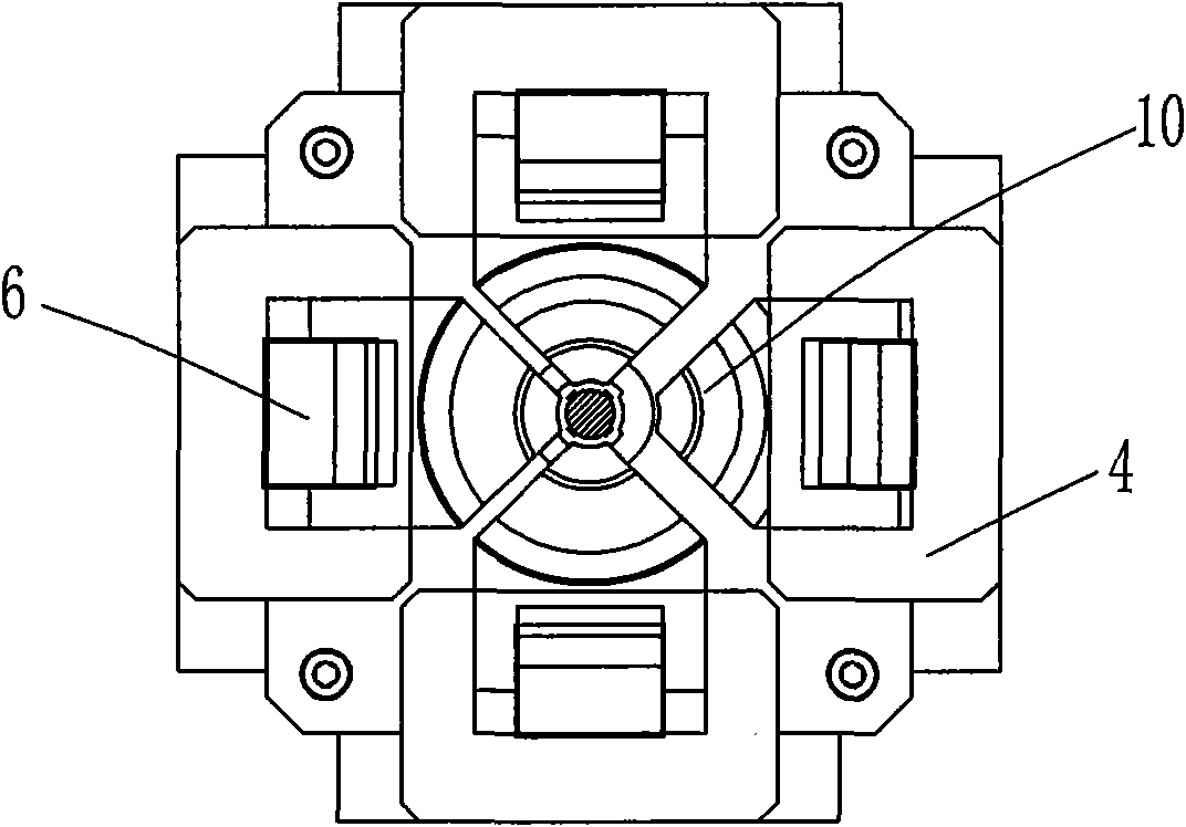
[0019] Example: Combine figure 1 , 2 , the synchronous clamping and riveting device of the present embodiment is based on the horizontal fixed plate 3 on the frame, and four baffle plates 8 and four guides are vertically fixed on the fixed plate with the workpiece 13 to be clamped as the center. Slot plate 4, each baffle plate and guide trough plate form a pair, and each baffle plate 8 and each guide trough plate 4 are respectively located on the circumference of the inner and outer circles with the workpiece 13 to be clamped as the center of the circle;

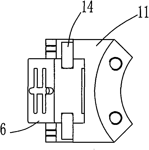
[0020] A guide plate 6 that penetrates the fixed plate 3 longitudinally is arranged between each pair of baffle plate 8 and the guide groove plate 4, and a guide groove for longitudinally guiding the guide plate 6 is formed between the baffle plate and the corresponding guide groove plate; One end of the guide plate 6 extending out of the bottom surface of the fixed plate 3 is jointly fixedly connected on a horizontal suppo...


PUM


Abstract

The invention discloses a self-centering radial synchronous clamping and riveting device, which can convert the axial motion of guide plates arranged on a drive rod pushed by a single drive source into the synchronous radial motion of a plurality of clamping block-mounting plates in order to achieve the purpose of accurately clamping and riveting shaft workpieces. The invention can be widely used for workpiece clamping in mechanical machining and automatic centering and clamping in automobile part assembly, and can be used as an industrial manipulator execution mechanism to clamp workpieces, and if clamping blocks are substituted by riveting tools, the invention can be used in cases requiring high centering, clamping and riveting precision, such as radial workpiece riveting.

Description

Technical field: [0001] The invention relates to a self-centering radial synchronous clamping and riveting device. Background technique: [0002] In most mechanical processing, assembly, clamping and other mechanisms, four cylinders are generally arranged in four directions to drive four chucks to clamp the workpiece, or a connecting rod mechanism is used, and one cylinder drives the connecting rod mechanism to rotate around the fixed workpiece. Points do arc motion, which needs to calculate the arc motion trajectory, which adapts to a single variety of workpieces and small clamping force. [0003] To sum up, the disadvantages of synchronous movement in multiple directions above are: poor precision, insufficient clamping force, inability to self-center, and many driving sources. Multi-directional clamping requires the support of multiple systems, such as To achieve four-direction synchronous clamping, if a system is to be used, servo closed-loop control is required, the hyd...

Claims


Application Information

Patent Timeline
IPC IPC(8): B23Q3/06B21D39/00
Inventor 余来宏付代勤张坚张友山张玮李孝荣
Owner HEFEI PRESSURE MACHINERY
Why Eureka
Try Eureka