
Combined fixture for cast crossbeams

A beam and fixture technology, applied in the direction of manufacturing tools, clamping, support, etc., can solve the problems of difficult processing, increase production and manufacturing costs, and many handling times, and achieve the effect of reducing production and handling costs, ensuring angular accuracy, and reducing processes.

Inactive Publication Date: 2010-08-04
济南中森机械制造有限公司
View PDF5 Cites 12 Cited by
  • Summary
  • Abstract
  • Description
  • Claims
  • Application Information

AI Technical Summary

Problems solved by technology

[0003] 1. Multi-process processing. This product has many holes processed, including the processing holes a, c and inclined holes b on the end surface, and they are distributed on different planes. It requires multi-station processing in different steps. The number of positioning reference replacements is large, and the handling cost is increased. and time consumption;
[0004] 2. The processing is difficult and the precision is high. The angle β of the center line of the eight oblique holes b is 48°17′, and the two sides are asymmetrical structures;
[0005] 3. Heavy weight and low efficiency. The product is time-consuming, labor-intensive and low-efficiency in terms of handling and operation.
[0006] Therefore, it is not suitable for long-term mass production, the number of handling is large, the quality cannot be stabilized, and the cost is too high.
This will undoubtedly greatly increase the manufacturing cost

Method used


Image

  • Combined fixture for cast crossbeams
  • Combined fixture for cast crossbeams
  • Combined fixture for cast crossbeams

Examples


Embodiment Construction

[0031] The present invention will be described in further detail below in conjunction with the accompanying drawings and specific embodiments, so that those skilled in the art can better understand the present invention.

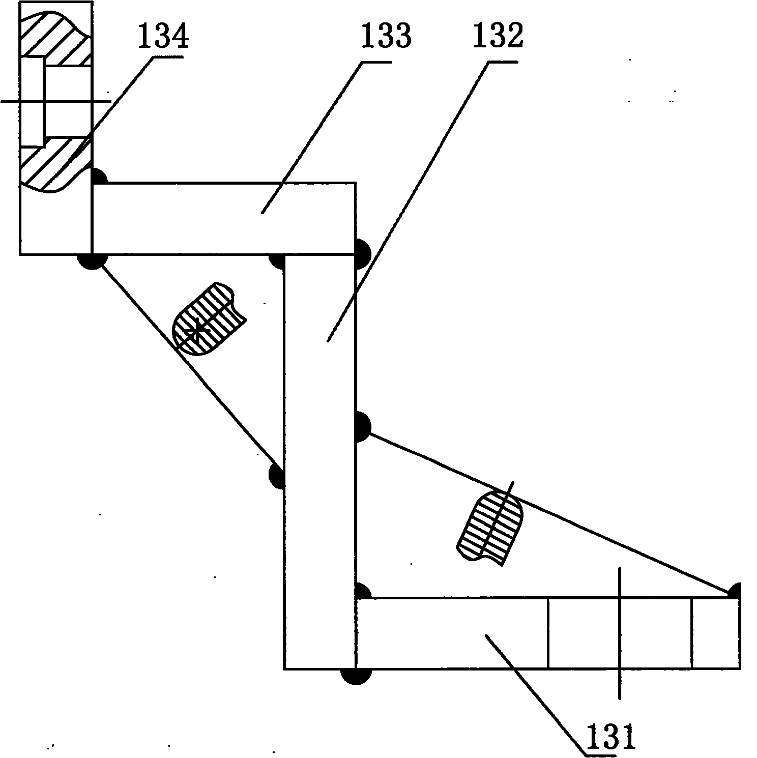
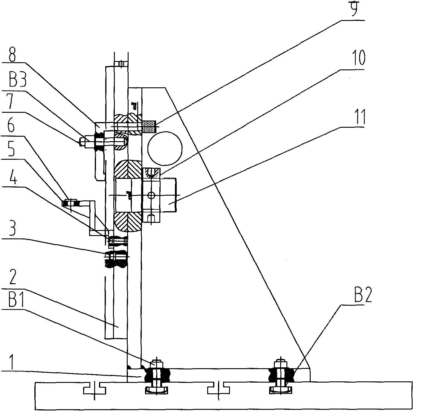
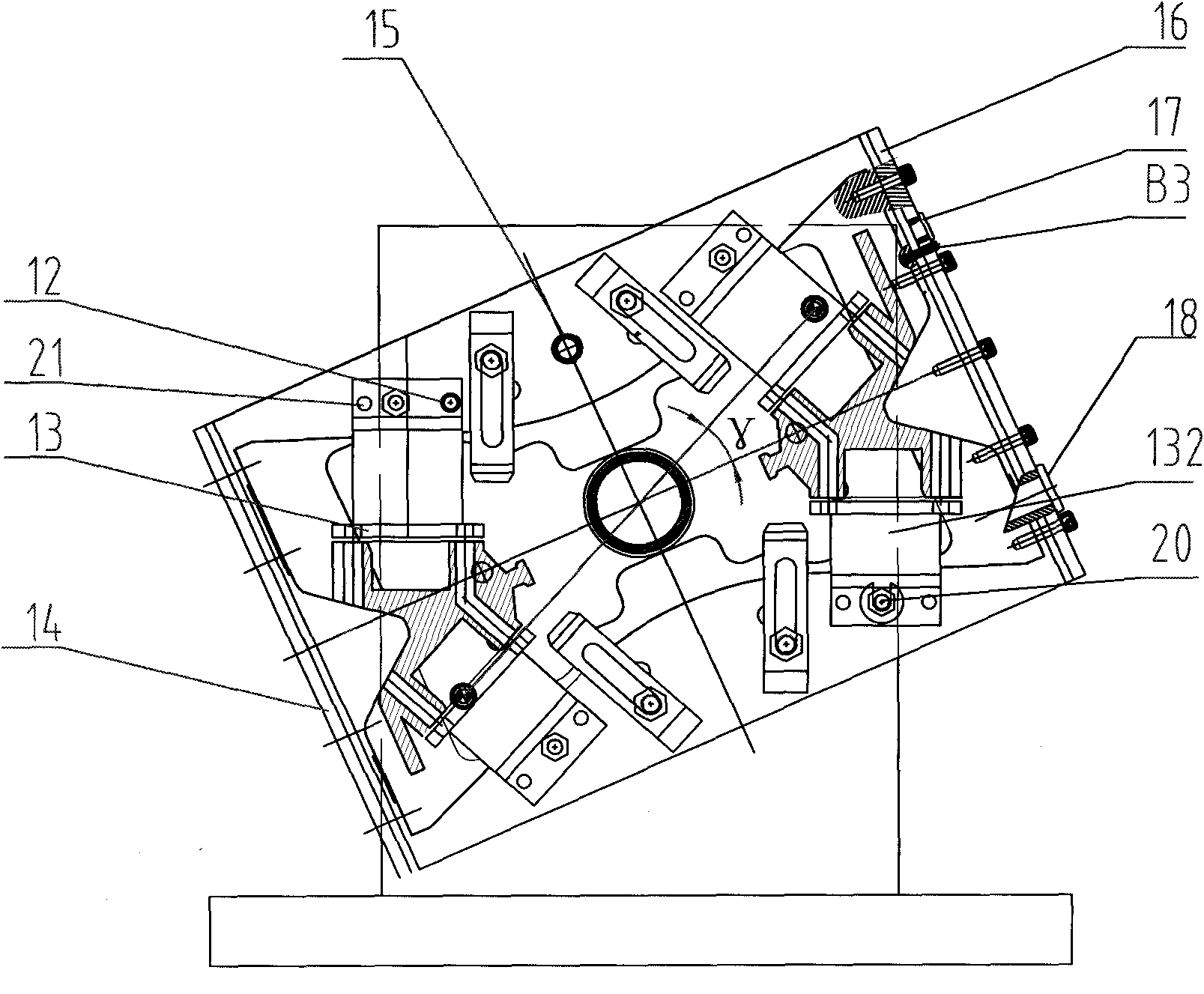
[0032] Such as figure 1 , 2 A casting crossbeam composite fixture is shown, comprising a fixed seat 1, a rotary plate 2, an end hole drilling template 14, at least two inclined hole drilling templates 13 and several clamping parts, and the fixed seat 1 has a The installation surface 1-1 and a fixed surface 1-2 perpendicular to the installation surface 1-1; the rotary plate 2 is rotatably mounted on the fixed surface 1-2 through the connecting shaft 11 and positioned by the shaft with the bushing 15; The two end hole drilling templates 14 are fixed on the two sides of the rotary plate 2, and the surface is provided with mold holes corresponding to the holes to be processed on both sides of the cast beam, and are positioned by the pin B3; the inclined hole d...


PUM


Abstract

The invention discloses a combined fixture for cast crossbeams, which comprises a fixed seat, a rotary plate, two end hole drill plates, at least two inclined hole drill plates and a plurality of clamping parts; the fixed seat is provided with a mounting surface connected with a drilling machine workbench and a fixing surface perpendicular to the mounting surface; the rotary plate is rotatably mounted on the fixing surface through a connecting shaft; the end hole drill plates are fixed on both sides of the rotary plate, and the surfaces of the end hole drill plates are provides with die holes corresponding to both sides of a cast crossbeam to be drilled; the inclined hole drill plates are mounted on the surface of the rotary plate, and each inclined hole drill plate is provided with drill plate holes corresponding to the positions and sizes of inclined holes; and the clamping parts are detachably mounted on the rotary plate, and are used for mounting the cast crossbeam on the rotary plate. The invention is integrated with multiple processes for machining, positioning is uniform, the number of processes is reduced, the carrying cost is reduced, and the efficiency is increased.

Description

technical field [0001] The invention relates to a casting beam composite fixture, in particular to a fixture which is arranged on a radial drilling machine workbench and processes each hole of a casting beam through rotary positioning. Background technique [0002] The car beam is an important part of the car, such as image 3 , 4 Shown is a schematic diagram of the beam structure of a heavy-duty vehicle, in view of the fact that the product is a complex, asymmetric large-scale product. The following problems exist in its actual processing: [0003] 1. Multi-process processing. This product has many holes processed, including the processing holes a, c and inclined holes b on the end surface, and they are distributed on different planes. It requires multi-station processing in different steps. The number of positioning reference replacements is large, and the handling cost is increased. and time consumption; [0004] 2. The processing is difficult and the precision is high...

Claims


Application Information

Patent Timeline
Patent Type & Authority Applications(China)
IPC IPC(8): B23Q3/06B23B47/28B23B49/02
Inventor 白江坤王军凯崔若平
Owner 济南中森机械制造有限公司
Learn More